

Owner's Manual - Smarthome
Owner's Manual - Smarthome
Owner's Manual - Smarthome

Create successful ePaper yourself
Turn your PDF publications into a flip-book with our unique Google optimized e-Paper software.
14 Multi-Wave PE653-PE953 Installation Guide<br />
Wiring Instructions<br />
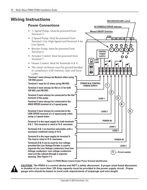
Power Connections<br />
• 1- Speed Pump: Must be powered from<br />
Terminal 3.<br />
• 2-Speed Pump: Must be powered from<br />
Terminal 3 for High-Speed and Terminal 4 for<br />
Low-Speed.<br />
• Booster Pump: Must be powered from<br />
Terminal 6.<br />
• Actuator Control: Must be powered from<br />
Terminal 7.<br />
• Heater Control: Must be Terminals 8 & 9.<br />
• The metal enclosure must be ground bonded<br />
in compliance with national, state and local<br />
codes.<br />
Terminal 1 must always be Neutral when using<br />
120 VAC power.<br />
Terminal 1 must be L2 when using 240 VAC.<br />
Terminal 2 must always be Hot or L1 for both<br />
120 VAC and 240 VAC.<br />
Terminal 3 must always be connected to the Hot<br />
terminal of the pump.<br />
Terminal 3 must always be connected to the<br />
HIGH SPEED terminal of a 2-speed pump.<br />
POWER IN & CONTROL<br />
POWER SUPPLY<br />
AC POWER & STATUS indicator<br />
<strong>Manual</strong> ON/OFF Switches<br />
120V<br />
240V<br />
CONTROL<br />
POWER<br />
SUPPLY<br />
LOAD 1<br />
INCLUDE/EXCLUDE switch<br />
1<br />
1 2 3 4 5<br />
1 2 3 4 5 6 7 8 9<br />
2<br />
3<br />
4<br />
Terminal 4 must always be connected to the<br />
LOW SPEED terminal of a 2-speed pump when<br />
using a 2-speed motor.<br />
Terminal 5 is the input supply for both terminals<br />
6 & 7. This terminal is rated at 15 A. maximum.<br />
Terminals 6 & 7 are function selectable with a<br />
maximum combined rating of 15 A.<br />
LOAD 2<br />
POWER IN<br />
LOAD 3<br />
LOAD 4<br />
5<br />
Terminal 8 is the input supply for terminal 9.<br />
The load is rated at 15 A. maximum.<br />
Terminals 8 & 9 can be used for low voltage<br />
provided the Low Voltage Divider is used to<br />
separate the Low Voltage conductors from Line<br />
Voltage conductors. Low voltage conductors<br />
must exit the cabinet through a separate<br />
opening. (See Figure 3-1)<br />
Figure 3-2 PE653 Master Control Center Power Terminal identification<br />
POWER IN<br />
LOAD 5<br />
1 = Circuit number<br />
CAUTION: The PE653 is a control device and NOT a safety disconnect. A proper sized fused disconnect<br />
or breaker of no more than 125 Amp capacity must be provided in the power supply circuit. Proper<br />
gauge wire should be based on local code requirements of amperage and wire length.<br />
Copyright © 2010 Intermatic, Inc.


