

Owner's Manual - Smarthome
Owner's Manual - Smarthome
Owner's Manual - Smarthome

You also want an ePaper? Increase the reach of your titles
YUMPU automatically turns print PDFs into web optimized ePapers that Google loves.
Three: PE653 Receiving Device Installation 35<br />
Low-Voltage Wiring<br />
Water Temperature Sensor<br />
The Multi-Wave Control System comes equipped with<br />
a Water Temperature Sensor. This sensor is needed<br />
to monitor both the pool and spa water temperature<br />
depending on the position of the diverter valves. It<br />
must be installed for the thermostat control to work.<br />
Power must be disconnected when connecting the<br />
temp sensor. Only an Intermatic Sensor will work<br />
with this controller. Follow these directions to install<br />
and mount the water temperature sensor.<br />
1. Drill a 3/8” hole in the pipe between the filter<br />
pump and filter and install the Water Temperature<br />
Sensor with hose clamp (not provided). Ensure the<br />
O-ring is in place.<br />
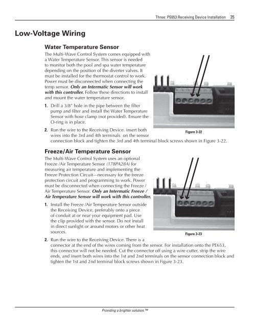
2. Run the wire to the Receiving Device. insert both<br />
Figure 3-22<br />
wires into the 3rd and 4th terminals on the sensor<br />
connection block and tighten the 3rd and 4th terminal block screws shown in Figure 3-22.<br />
Freeze/Air Temperature Sensor<br />
The Multi-Wave Control System uses an optional<br />
Freeze /Air Temperature Sensor (178PA28A) for<br />
measuring air temperature and implementing the<br />
Freeze Protection Circuit—necessary for the freeze<br />
protection circuit and programming to work. Power<br />
must be disconnected when connecting the Freeze /<br />
Air Temperature Sensor. Only an Intermatic Freeze /<br />
Air Temperature Sensor will work with this controller.<br />
1. Install the Freeze /Air Temperature Sensor outside<br />
the Receiving Device, preferably onto a piece<br />
of conduit at or near your equipment pad. Use<br />
the clip provided with the sensor. Do not install<br />
in direct sunlight or around motors or other heat<br />
sources.<br />
Figure 3-23<br />
2. Run the wire to the Receiving Device. There is a<br />
connector at the end of the wires coming from the sensor. For installation onto the PE653,<br />
this connector will not be needed. Cut the connector off using a wire cutter, strip the wire<br />
ends, and insert both wires into the 1st and 2nd terminals on the sensor connection block and<br />
tighten the 1st and 2nd terminal block screws shown in Figure 3‐23.<br />
Providing a brighter solution.


