

Owner's Manual - Smarthome
Owner's Manual - Smarthome
Owner's Manual - Smarthome

Create successful ePaper yourself
Turn your PDF publications into a flip-book with our unique Google optimized e-Paper software.
Three: PE653 Receiving Device Installation 37<br />
The actuators must be installed to automatically rotate your valves between the pool and spa<br />
plumbing. The 24 VAC power for the Valve Actuators is produced by a transformer in the<br />
P4243ME. All power to both units must be turned OFF when connecting the black and white<br />
actuator control leads to the PE653 (see diagram above). Refer to the installation and wiring<br />
directions for the P4243ME Actuator Control and PE24VA Actuators for additional instructions<br />
for each unit.Remove power from the P4243ME and the Multi-Wave Receiving Device.<br />
1.<br />
2.<br />
3.<br />
4.<br />
5.<br />
6.<br />
7.<br />
Attach the valve actuators (PE24VA) to the water valves. (See instructions included with<br />
actuators).<br />
Run the actuator cable(s) to the P4243ME control through the low voltage raceway.<br />
Remove the access door at the top right of the P4243ME mechanism.<br />
Insert the three-pin connector of the motorized valve actuator to any of the three available<br />
connectors on the P4243ME circuit board.<br />
Connect 120 or 240 VAC power leads to the correct colored wires of the P4243ME<br />
transformer (see above).<br />
Connect the two Actuator Control wire leads as shown above in Figure 3-25.<br />
Apply power to both the PE653 and the P4243ME and synchronize the actuators as follows:<br />
a. Make sure that circuit number 4 is OFF (Green Load ON indicator is OFF). This indicates<br />
that the switch is in POOL mode.<br />
b. If either of the Actuators is positioned backwards, flip the switch on the back to reverse<br />
position.<br />
c. Turn circuit number 4 ON (Green Load ON indicator is ON). This indicates that the switch<br />
is in SPA mode.<br />
d. Verify that the Actuators are correctly synchronized with your installation.<br />
Fireman’s Switch Connection<br />
The Intermatic Multi-Wave Control System is capable of controlling most heaters or heat pumps<br />
in the market today. Circuit number 5 in the PE653 is configured to control the heater using the<br />
24 VAC thermostatic circuitry. Locate your type of heater in the following pages and follow the<br />
instructions for proper installation.<br />
Refer to the heater manufacturer’s installation and wiring manual if you do not find information<br />
regarding your specific brand or model of heater.<br />
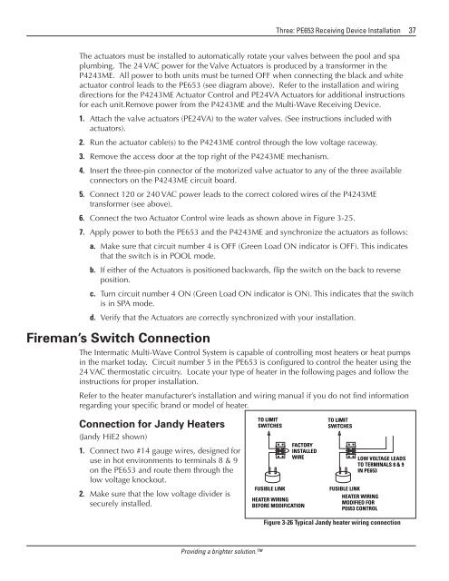
Connection for Jandy Heaters<br />
(Jandy HiE2 shown)<br />
1. Connect two #14 gauge wires, designed for<br />
use in hot environments to terminals 8 & 9<br />
on the PE653 and route them through the<br />
low voltage knockout.<br />
2. Make sure that the low voltage divider is<br />
securely installed.<br />
TO LIMIT<br />
SWITCHES<br />
FUSIBLE LINK<br />
FACTORY<br />
INSTALLED<br />
WIRE<br />
HEATER WIRING<br />
BEFORE MODIFICATION<br />
TO LIMIT<br />
SWITCHES<br />
FUSIBLE LINK<br />
HEATER WIRING<br />
MODIFIED FOR<br />
PE653 CONTROL<br />
LOW VOLTAGE LEADS<br />
TO TERMINALS 8 & 9<br />
IN PE653<br />
Figure 3-26 Typical Jandy heater wiring connection<br />
Providing a brighter solution.


