

Owner's Manual - Smarthome
Owner's Manual - Smarthome
Owner's Manual - Smarthome

Create successful ePaper yourself
Turn your PDF publications into a flip-book with our unique Google optimized e-Paper software.
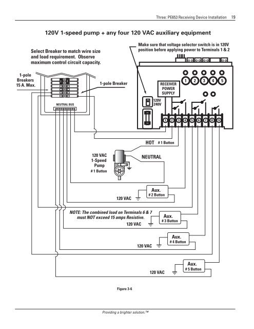
Three: PE653 Receiving Device Installation 19<br />
120V 1-speed pump + any four 120 VAC auxiliary equipment<br />
Select Breaker to match wire size<br />
and load requirement. Observe<br />
maximum control circuit capacity.<br />
Make sure that voltage selector switch is in 120V<br />
position before applying power to Terminals 1 & 2<br />
1-pole<br />
Breakers<br />
15 A. Max.<br />
1-pole Breaker<br />
RECEIVER<br />
POWER<br />
SUPPLY<br />
1 2 3 4 5<br />
NEUTRAL BUS<br />
120V<br />
240V<br />
1 2 3 4 5 6 7 8 9<br />
HOT<br />
# 1 Button<br />
120 VAC<br />
1-Speed<br />
Pump<br />
# 1 Button<br />
NEUTRAL<br />
120 VAC<br />
Aux.<br />
# 2 Button<br />
NOTE: The combined load on Terminals 6 & 7<br />
must NOT exceed 15 amps Resistive.<br />
120 VAC<br />
120 VAC<br />
Aux.<br />
# 3 Button<br />
Aux.<br />
# 4 Button<br />
120 VAC<br />
Aux.<br />
# 5 Button<br />
Figure 3-6<br />
Providing a brighter solution.


