

Owner's Manual - Smarthome
Owner's Manual - Smarthome
Owner's Manual - Smarthome

You also want an ePaper? Increase the reach of your titles
YUMPU automatically turns print PDFs into web optimized ePapers that Google loves.
s<br />
38 Multi-Wave PE653-PE953 Installation Guide<br />
3.<br />
4.<br />
Locate the Fireman’s switch terminal in the control section of the heater.<br />
Remove the factory installed jumper wire.<br />
5. Connect the other ends of the #14 gauge wires from Step #1 to the Fireman’s Switch terminal<br />
bar in place of the factory installed wire loop.<br />
6. Do not disconnect high limit or pressure switches.<br />
7. Turn the heater thermostat(s) to maximum setting.<br />
8. Turn the heater switch to the ON position.<br />
For dual thermostat heaters turn switch to Spa position.<br />
Provide wiring with insulation at least 3/64” thick and having a temperature rating of at least<br />
90°C.<br />
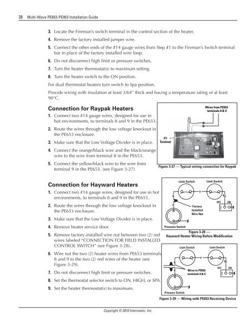
Connection for Raypak Heaters<br />
1. Connect two #14 gauge wires, designed for use in<br />
hot environments, to terminals 8 and 9 in the PE653.<br />
2. Route the wires through the low voltage knockout in<br />
the PE653 enclosure.<br />
3. Make sure that the Low Voltage Divider is in place.<br />
4. Connect the orange/black wire and the black/orange<br />
wire to the wire from terminal 8 in the PE653.<br />
5. Connect the yellow/black wire to the wire from<br />
terminal 9 in the PE653. (see Figure 3-27)<br />
P7<br />
Terminal<br />
Wires from PE653<br />
terminals 8 & 9<br />
Figure 3-27 — Typical wiring connection for Raypak<br />
Connection for Hayward Heaters<br />
1. Connect two #14 gauge wires, designed for use in hot<br />
environments, to terminals 8 and 9 in the PE653.<br />
2. Route the wires through the low voltage knockout in<br />
the PE653 enclosure.<br />
3. Make sure that the Low Voltage Divider is in place.<br />
4. Remove heater service door.<br />
5. Remove factory-installed wire nut between two (2) red<br />
wires labeled “CONNECTION FOR FIELD INSTALLED<br />
CONTROL SWITCH” (see Figure 3-28).<br />
6. Wire nut the two (2) heater wires from PE653 terminals<br />
8 and 9 to the two (2) red wires of the heater (see<br />
Figure 3-29).<br />
7. Do not disconnect high limit or pressure switches.<br />
8. Set the thermostat selector switch to ON, HIGH, or SPA.<br />
9. Set the heater thermostat(s) to maximum.<br />
R<br />
R<br />
Limit Switch<br />
VV<br />
Factory Factory<br />
Installed<br />
Installed<br />
Wire Nut<br />
Wire Nut<br />
Limit Switch<br />
OFF OFF<br />
BL BL<br />
ON ON<br />
Pressure Switch<br />
Pressure Switch<br />
Figure 3-28 —<br />
Hayward Heater Wiring Before Modification<br />
R<br />
R<br />
R<br />
R<br />
Pressure Switch<br />
Limit Switch<br />
Limit Switch<br />
V<br />
Wires to PE653<br />
terminals 8 & 9<br />
Wires to PE653<br />
terminals 8 & 9<br />
Limit Switch<br />
Limit Switch<br />
OFF<br />
BL<br />
ON<br />
Figure Pressure 3-29 Switch — Wiring with PE653 Receiving Device<br />
V<br />
OFF<br />
BL<br />
ON<br />
Copyright © 2010 Intermatic, Inc.


