

Owner's Manual - Smarthome
Owner's Manual - Smarthome
Owner's Manual - Smarthome

You also want an ePaper? Increase the reach of your titles
YUMPU automatically turns print PDFs into web optimized ePapers that Google loves.
RELAY 1 RELAY 2<br />
VALVES<br />
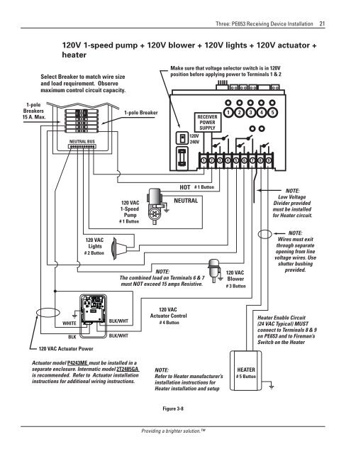
Three: PE653 Receiving Device Installation 21<br />
120V 1-speed pump + 120V blower + 120V lights + 120V actuator +<br />
heater<br />
Select Breaker to match wire size<br />
and load requirement. Observe<br />
maximum control circuit capacity.<br />
Make sure that voltage selector switch is in 120V<br />
position before applying power to Terminals 1 & 2<br />
1-pole<br />
Breakers<br />
15 A. Max.<br />
1-pole Breaker<br />
RECEIVER<br />
POWER<br />
SUPPLY<br />
1 2 3 4 5<br />
NEUTRAL BUS<br />
120V<br />
240V<br />
1 2 3 4 5 6 7 8 9<br />
120 VAC<br />
1-Speed<br />
Pump<br />
# 1 Button<br />
HOT<br />
NEUTRAL<br />
# 1 Button<br />
NOTE:<br />
Low Voltage<br />
Divider provided<br />
must be installed<br />
for Heater circuit.<br />
120 VAC<br />
Lights<br />
# 2 Button<br />
NOTE:<br />
The combined load on Terminals 6 & 7<br />
must NOT exceed 15 amps Resistive.<br />
120 VAC<br />
Blower<br />
# 3 Button<br />
NOTE:<br />
Wires must exit<br />
through separate<br />
opening from line<br />
voltage wires. Use<br />
shutter bushing<br />
provided.<br />
WHITE<br />
BLK<br />
120 VAC Actuator Power<br />
BLK/WHT<br />
BLK/WHT<br />
120 VAC<br />
Actuator Control<br />
# 4 Button<br />
Heater Enable Circuit<br />
(24 VAC Typical) MUST<br />
connect to Terminals 8 & 9<br />
on PE653 and to Fireman’s<br />
Switch on the Heater<br />
Actuator model P4243ME must be installed in a<br />
separate enclosure. Intermatic model 2T2485GA<br />
is recommended. Refer to Actuator installation<br />
instructions for additional wiring instructions.<br />
NOTE:<br />
Refer to Heater manufacturer’s<br />
installation instructions for<br />
Heater installation and setup<br />
HEATER<br />
# 5 Button<br />
Figure 3-8<br />
Providing a brighter solution.


