ALLEN BRADLEY 1747-L551 PLC Processor
ALLEN BRADLEY 1747-L551 PLC Processor
ALLEN BRADLEY 1747-L551 PLC Processor

Create successful ePaper yourself
Turn your PDF publications into a flip-book with our unique Google optimized e-Paper software.
Selecting Your Hardware Components<br />
2–3<br />
Principles of Machine Control<br />
You enter a logic program into the controller using the software. The<br />
logic program is based on your electrical relay print diagrams. It<br />
contains instructions that direct control of your application.<br />
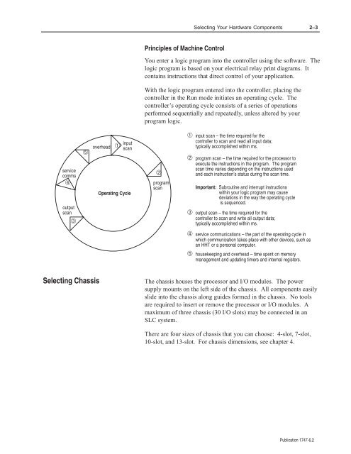
With the logic program entered into the controller, placing the<br />
controller in the Run mode initiates an operating cycle. The<br />
controller’s operating cycle consists of a series of operations<br />
performed sequentially and repeatedly, unless altered by your<br />
program logic.<br />
service<br />
comms<br />
➃<br />
output<br />
scan<br />
➂<br />
➄<br />
overhead<br />
➀<br />
input<br />
scan<br />
Operating Cycle<br />
➁<br />
program<br />
scan<br />
➀ input scan – the time required for the<br />
controller to scan and read all input data;<br />
typically accomplished within ms.<br />
➁ program scan – the time required for the processor to<br />
execute the instructions in the program. The program<br />
scan time varies depending on the instructions used<br />
and each instruction’s status during the scan time.<br />
Important: Subroutine and interrupt instructions<br />
within your logic program may cause<br />
deviations in the way the operating cycle<br />
is sequenced.<br />
➂ output scan – the time required for the<br />
controller to scan and write all output data;<br />
typically accomplished within ms.<br />
➃ service communications – the part of the operating cycle in<br />
which communication takes place with other devices, such as<br />
an HHT or a personal computer.<br />
➄ housekeeping and overhead – time spent on memory<br />
management and updating timers and internal registers.<br />
Selecting Chassis<br />
The chassis houses the processor and I/O modules. The power<br />
supply mounts on the left side of the chassis. All components easily<br />
slide into the chassis along guides formed in the chassis. No tools<br />
are required to insert or remove the processor or I/O modules. A<br />
maximum of three chassis (30 I/O slots) may be connected in an<br />
SLC system.<br />
There are four sizes of chassis that you can choose: 4-slot, 7-slot,<br />
10-slot, and 13-slot. For chassis dimensions, see chapter 4.<br />
Publication <strong>1747</strong>-6.2

![Documentation [PDF] - Canada France Hawaii Telescope ...](https://img.yumpu.com/26965302/1/190x245/documentation-pdf-canada-france-hawaii-telescope-.jpg?quality=85)