ALLEN BRADLEY 1747-L551 PLC Processor
ALLEN BRADLEY 1747-L551 PLC Processor
ALLEN BRADLEY 1747-L551 PLC Processor

You also want an ePaper? Increase the reach of your titles
YUMPU automatically turns print PDFs into web optimized ePapers that Google loves.
Installing Your Hardware Components<br />
6–3<br />
Installing Your Memory<br />
Module<br />
Always turn off power to the controller before removing the<br />
processor or inserting or removing the memory module. This guards<br />
against possible damage to the module and also undesired processor<br />
faults. Memory modules are mounted in carriers or have connectors<br />
that are “keyed” to guard against improper installation.<br />
!<br />
ATTENTION: To avoid potential damage to the<br />
memory modules, handle them by the ends of the<br />
carrier or edges of the plastic housing. Skin oil and dirt<br />
can corrode metallic surfaces, inhibiting electrical<br />
contact. Also, do not expose memory modules to<br />
surfaces or areas that may typically hold an<br />
electrostatic charge. Electrostatic charges can alter or<br />
destroy memory.<br />
1. If the processor module is installed in the chassis, remove the<br />
module by pressing the retainer clips at both the top and bottom<br />
of the module and sliding it out.<br />
2. Locate the socket (or connector if you have an SLC 5/03,<br />
SLC 5/04, or SLC 5/05) on the processor board. Then place the<br />
memory module into the socket or onto the connector and press<br />
firmly in place.<br />
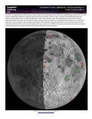
Side View of SLC <strong>Processor</strong><br />
<strong>1747</strong>-L511, -L514, and -L524 Series B<br />
Side View of SLC <strong>Processor</strong><br />
<strong>1747</strong>-L524 Series C<br />
Side View of SLC <strong>Processor</strong><br />
<strong>1747</strong>-L531, -L532, -L541, -L542, -L543,<br />
-<strong>L551</strong>, -L552, and -L553<br />
Memory<br />
Module<br />
Socket<br />
Jumper J1<br />
(Note: Jumper J1 not<br />
on <strong>1747</strong>-L511)<br />
Memory<br />
Module<br />
Socket<br />
Jumper J1<br />
Memory<br />
Module<br />
Connector<br />
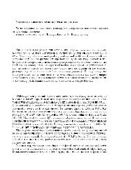
3. Place jumper J1 as shown below.<br />
<strong>Processor</strong> Type <strong>1747</strong>-M1, -M2, -M3 <strong>1747</strong>-M4 Invalid Settings<br />
<strong>1747</strong>-L514, -L524<br />
Series B and Series C<br />
<strong>1747</strong>-L511, -L531, -L532,<br />
-L541, -L542, -L543, -<strong>L551</strong>,<br />
-L552, and -L553<br />
No Jumper J1 No Jumper J1 No Jumper J1<br />
Publication <strong>1747</strong>-6.2

![Documentation [PDF] - Canada France Hawaii Telescope ...](https://img.yumpu.com/26965302/1/190x245/documentation-pdf-canada-france-hawaii-telescope-.jpg?quality=85)