GL900 USER'S MANUAL - Graphtec
GL900 USER'S MANUAL - Graphtec
GL900 USER'S MANUAL - Graphtec

Create successful ePaper yourself
Turn your PDF publications into a flip-book with our unique Google optimized e-Paper software.
Checks and Preparation<br />
Low-voltage input terminal<br />
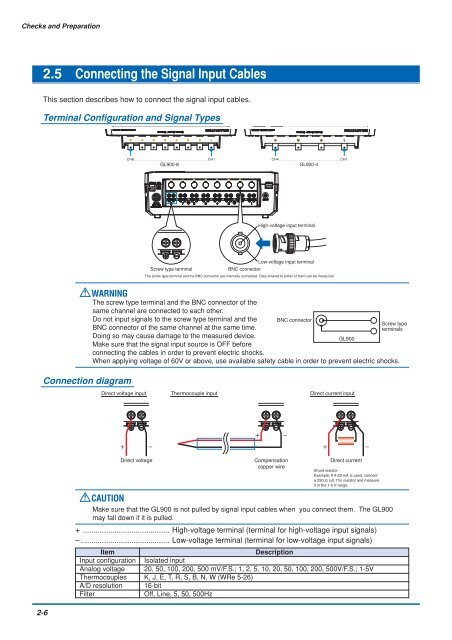
2.5 Connecting the Signal Input Cables<br />
This section describes how to connect the signal input cables.<br />
Terminal Configuration and Signal Types<br />
CH8............................................CH1<br />
<strong>GL900</strong>-8<br />
CH4.....................................CH1<br />
<strong>GL900</strong>-4<br />
High-voltage input terminal<br />
Low-voltage input terminal<br />
Screw type terminal<br />
BNC connector<br />
The screw type terminal and the BNC connector are internally connected. Data entered to either of them can be measured.<br />
WARNING<br />
The screw type terminal and the BNC connector of the<br />
same channel are connected to each other.<br />
Do not input signals to the screw type terminal and the BNC connector<br />
BNC connector of the same channel at the same time.<br />
Doing so may cause damage to the measured device.<br />
<strong>GL900</strong><br />
Make sure that the signal input source is OFF before<br />
connecting the cables in order to prevent electric shocks.<br />
When applying voltage of 60V or above, use available safety cable in order to prevent electric shocks.<br />
Screw type<br />
terminals<br />
Connection diagram<br />
Direct voltage input<br />
Thermocouple input<br />
Direct current input<br />
Direct voltage<br />
Compensation<br />
copper wire<br />
Direct current<br />
Shunt resistor<br />
Example: If 4-20 mA is used, connect<br />
a 250 Ω (±0.1%) resistor and measure<br />
it in the 1-5 V range.<br />
CAUTION<br />
Make sure that the <strong>GL900</strong> is not pulled by signal input cables when you connect them. The <strong>GL900</strong><br />
may fall down if it is pulled.<br />
+ ......................................... High-voltage terminal (terminal for high-voltage input signals)<br />
– .......................................... Low-voltage terminal (terminal for low-voltage input signals)<br />
Item<br />
Description<br />
Input configuration Isolated input<br />
Analog voltage 20, 50, 100, 200, 500 mV/F.S.; 1, 2, 5, 10, 20, 50, 100, 200, 500V/F.S.; 1-5V<br />
Thermocouples K, J, E, T, R, S, B, N, W (WRe 5-26)<br />
A/D resolution 16-bit<br />
Filter<br />
Off, Line, 5, 50, 500Hz<br />
2-6