GL900 USER'S MANUAL - Graphtec
GL900 USER'S MANUAL - Graphtec
GL900 USER'S MANUAL - Graphtec

You also want an ePaper? Increase the reach of your titles
YUMPU automatically turns print PDFs into web optimized ePapers that Google loves.
Settings and Measurement<br />
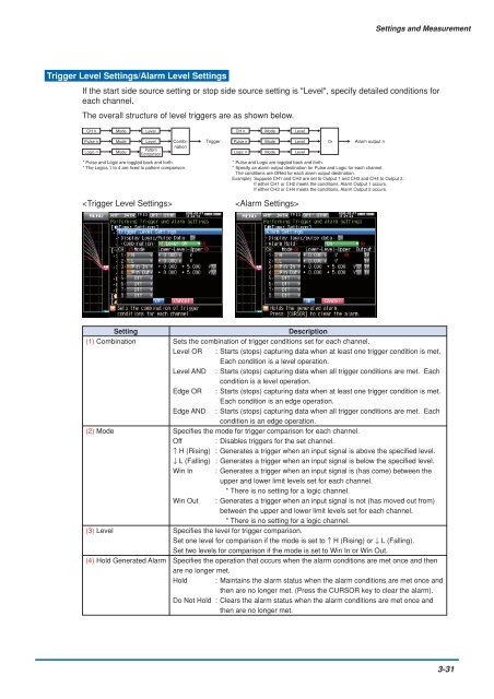
Trigger Level Settings/Alarm Level Settings<br />
If the start side source setting or stop side source setting is "Level", specify detailed conditions for<br />
each channel.<br />
The overall structure of level triggers are as shown below.<br />
CH n Mode Level<br />
Pulse n Mode Level Combination<br />
Trigger<br />
Logic n Mode<br />
Pattern<br />
Comparison<br />
* Pulse and Logic are toggled back and forth.<br />
* The Logics 1 to 4 are fixed to pattern comparison.<br />
<br />
CH n Mode Level<br />
Pulse n Mode Level Or Alarm output n<br />
Logic n Mode Level<br />
* Pulse and Logic are toggled back and forth.<br />
* Specify an alarm output destination for Pulse and Logic for each channel.<br />
The conditions are ORed for each alarm output destination.<br />
Example) Suppose CH1 and CH2 are set to Output 1 and CH3 and CH4 to Output 2.<br />
If either CH1 or CH2 meets the conditions, Alarm Output 1 occurs.<br />
If either CH3 or CH4 meets the conditions, Alarm Output 2 occurs.<br />
<br />
Setting<br />
Description<br />
(1) Combination Sets the combination of trigger conditions set for each channel.<br />
Level OR : Starts (stops) capturing data when at least one trigger condition is met.<br />
Each condition is a level operation.<br />
Level AND : Starts (stops) capturing data when all trigger conditions are met. Each<br />
condition is a level operation.<br />
Edge OR : Starts (stops) capturing data when at least one trigger condition is met.<br />
Each condition is an edge operation.<br />
Edge AND : Starts (stops) capturing data when all trigger conditions are met. Each<br />
condition is an edge operation.<br />
(2) Mode Specifies the mode for trigger comparison for each channel.<br />
Off : Disables triggers for the set channel.<br />
↑ H (Rising) : Generates a trigger when an input signal is above the specified level.<br />
↓ L (Falling) : Generates a trigger when an input signal is below the specified level.<br />
Win In : Generates a trigger when an input signal is (has come) between the<br />
upper and lower limit levels set for each channel.<br />
* There is no setting for a logic channel.<br />
Win Out : Generates a trigger when an input signal is not (has moved out from)<br />
between the upper and lower limit levels set for each channel.<br />
* There is no setting for a logic channel.<br />
(3) Level Specifies the level for trigger comparison.<br />
Set one level for comparison if the mode is set to ↑ H (Rising) or ↓ L (Falling).<br />
Set two levels for comparison if the mode is set to Win In or Win Out.<br />
(4) Hold Generated Alarm Specifies the operation that occurs when the alarm conditions are met once and then<br />
are no longer met.<br />
Hold : Maintains the alarm status when the alarm conditions are met once and<br />
then are no longer met. (Press the CURSOR key to clear the alarm).<br />
Do Not Hold : Clears the alarm status when the alarm conditions are met once and<br />
then are no longer met.<br />
3-31