Sustainable Construction A Life Cycle Approach in Engineering
Sustainable Construction A Life Cycle Approach in Engineering
Sustainable Construction A Life Cycle Approach in Engineering

You also want an ePaper? Increase the reach of your titles
YUMPU automatically turns print PDFs into web optimized ePapers that Google loves.
3 USE OF SIMULATION PROGRAM PVSYST V3.3<br />
The second stage of the proposed method is us<strong>in</strong>g the simulation program PVSYST V3.3 to<br />
f<strong>in</strong>d the optimum tilt angle for the previously determ<strong>in</strong>ed optimum orientation. There are several<br />
simulation programs that are used for simulat<strong>in</strong>g energy use or production of build<strong>in</strong>gs. The<br />
most accepted one of them throughout the world is PVSYST. PVSYST V3.3 is a PC software<br />
package for the study, siz<strong>in</strong>g and data analysis of complete PV systems. It deals with gridconnected,<br />
stand-alone and DC-grid (public transport) PV systems, and <strong>in</strong>cludes extensive meteo<br />
and PV systems components databases, as well as general solar energy tools. This software<br />
is geared to the needs of architects, eng<strong>in</strong>eers, researchers. It is also very helpful for educational<br />
tra<strong>in</strong><strong>in</strong>g. (WEB_1, 2004) Therefore it is used for the simulation of the BIPV modules. There are<br />
different versions of the program. Version V3.3 is used <strong>in</strong> this study.<br />
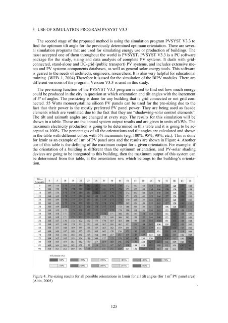
The pre-siz<strong>in</strong>g function of the PVSYST V3.3 program is used to f<strong>in</strong>d out how much energy<br />
could be produced <strong>in</strong> the city <strong>in</strong> question at which orientation and tilt angles with the <strong>in</strong>crement<br />
of 5º of angles. The pre-siz<strong>in</strong>g is done for any build<strong>in</strong>g that is grid connected or not grid connected.<br />
55 Watts monocrystall<strong>in</strong>e silicon PV panels can be used for the pre-siz<strong>in</strong>g due to the<br />
fact that their power is the mostly preferred PV panel power. They are be<strong>in</strong>g used as facade<br />
elements which are ventilated due to the fact that they are “shadow<strong>in</strong>g-solar control elements”.<br />
The tilt and azimuth angles are changed at every step. The results for this simulation will be<br />
shown <strong>in</strong> a table. These are the annual system output results and are given <strong>in</strong> units of kWh. The<br />
maximum electricity production is go<strong>in</strong>g to be determ<strong>in</strong>ed <strong>in</strong> this table and it is go<strong>in</strong>g to be accepted<br />
as 100%. The percentages of all the orientations and tilt angles are calculated and shown<br />
<strong>in</strong> the table with different colors with 5% <strong>in</strong>crements (e.g. 100%, 95%, 90%, etc.). This is done<br />
for Izmir as an example of 1m 2 of PV panel area and the results are shown <strong>in</strong> Figure 4. Another<br />
use of this table is the def<strong>in</strong><strong>in</strong>g of the maximum output for a given orientation. For example, if<br />
the orientation of a build<strong>in</strong>g is different than the optimum orientation, and PV-solar shad<strong>in</strong>g<br />
devices are go<strong>in</strong>g to be <strong>in</strong>tegrated to this build<strong>in</strong>g, then the maximum output of this system can<br />
be determ<strong>in</strong>ed from this table, at the orientation row which belongs to the build<strong>in</strong>g‟s orientation.<br />
Figure 4. Pre-siz<strong>in</strong>g results for all possible orientations <strong>in</strong> Izmir for all tilt angles (for 1 m 2 PV panel area)<br />
(Alt<strong>in</strong>, 2005)<br />
125
![Weibull [Compatibility Mode]](https://img.yumpu.com/48296360/1/190x134/weibull-compatibility-mode.jpg?quality=85)