Sustainable Construction A Life Cycle Approach in Engineering
Sustainable Construction A Life Cycle Approach in Engineering
Sustainable Construction A Life Cycle Approach in Engineering

Create successful ePaper yourself
Turn your PDF publications into a flip-book with our unique Google optimized e-Paper software.
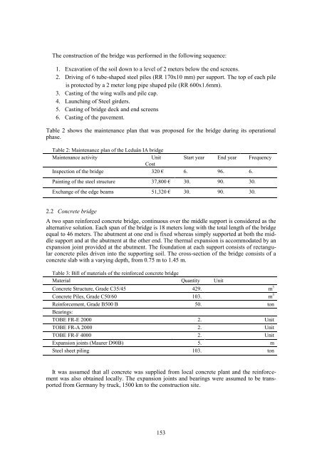
The construction of the bridge was performed <strong>in</strong> the follow<strong>in</strong>g sequence:<br />
1. Excavation of the soil down to a level of 2 meters below the end screens.<br />
2. Driv<strong>in</strong>g of 6 tube-shaped steel piles (RR 170x10 mm) per support. The top of each pile<br />
is protected by a 2 meter long pipe shaped pile (RR 600x1.6mm).<br />
3. Cast<strong>in</strong>g of the w<strong>in</strong>g walls and pile cap.<br />
4. Launch<strong>in</strong>g of Steel girders.<br />
5. Cast<strong>in</strong>g of bridge deck and end screens<br />
6. Cast<strong>in</strong>g of the pavement.<br />
Table 2 shows the ma<strong>in</strong>tenance plan that was proposed for the bridge dur<strong>in</strong>g its operational<br />
phase.<br />
Table 2: Ma<strong>in</strong>tenance plan of the Leduån IA bridge<br />
Ma<strong>in</strong>tenance activity<br />
Unit Start year End year Frequency<br />
Cost<br />
Inspection of the bridge 320 € 6. 96. 6.<br />
Pa<strong>in</strong>t<strong>in</strong>g of the steel structure 37,800 € 30. 90. 30.<br />
Exchange of the edge beams 51,320 € 30. 90. 30.<br />
2.2 Concrete bridge<br />
A two span re<strong>in</strong>forced concrete bridge, cont<strong>in</strong>uous over the middle support is considered as the<br />
alternative solution. Each span of the bridge is 18 meters long with the total length of the bridge<br />
equal to 46 meters. The abutment at one end is fixed whereas simply supported at both the middle<br />
support and at the abutment at the other end. The thermal expansion is accommodated by an<br />
expansion jo<strong>in</strong>t provided at the abutment. The foundation at each support consists of rectangular<br />
concrete piles driven <strong>in</strong>to the support<strong>in</strong>g soil. The cross-section of the bridge consists of a<br />
concrete slab with a vary<strong>in</strong>g depth, from 0.75 m to 1.45 m.<br />
Table 3: Bill of materials of the re<strong>in</strong>forced concrete bridge<br />
Material Quantity Unit<br />
Concrete Structure, Grade C35/45 429. m 3<br />
Concrete Piles, Grade C50/60 103. m 3<br />
Re<strong>in</strong>forcement, Grade B500 B 50. ton<br />
Bear<strong>in</strong>gs:<br />
TOBE FR-E 2000 2. Unit<br />
TOBE FR-A 2000 2. Unit<br />
TOBE FR-F 4000 2. Unit<br />
Expansion jo<strong>in</strong>ts (Maurer D90B) 5. m<br />
Steel sheet pil<strong>in</strong>g 103. ton<br />
It was assumed that all concrete was supplied from local concrete plant and the re<strong>in</strong>forcement<br />
was also obta<strong>in</strong>ed locally. The expansion jo<strong>in</strong>ts and bear<strong>in</strong>gs were assumed to be transported<br />
from Germany by truck, 1500 km to the construction site.<br />
153
![Weibull [Compatibility Mode]](https://img.yumpu.com/48296360/1/190x134/weibull-compatibility-mode.jpg?quality=85)