

Fisher® FIELDVUE DVC6200 Digital Valve Controller
Fisher® FIELDVUE DVC6200 Digital Valve Controller
Fisher® FIELDVUE DVC6200 Digital Valve Controller

Create successful ePaper yourself
Turn your PDF publications into a flip-book with our unique Google optimized e-Paper software.
Maintenance and Troubleshooting<br />
July 2012<br />
Instruction Manual<br />
D103605X012<br />
4. Ensure that the O‐ring (key 39) and screen (key 231) stay in the module base and do not come out with the I/P<br />
converter (key 41).<br />
Replacing the I/P Converter<br />
1. Refer to figure 6‐2. Inspect the condition of the O‐ring (key 39) and screen (key 231) in the module base (key 2).<br />
Replace them, if necessary. Apply silicone lubricant to the O‐rings.<br />
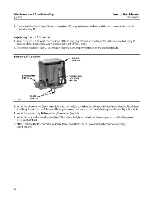
2. Ensure the two boots (key 210) shown in figure 6‐3 are properly installed on the electrical leads.<br />
Figure 6‐3. I/P Converter<br />
SHROUD<br />
(KEY 169)<br />
I/P CONVERTER<br />
(KEY 41)<br />
SOCKET‐HEAD<br />
SCREWS (4)<br />
(KEY 23)<br />
W9328<br />
BOOTS<br />
(KEY 210)<br />
3. Install the I/P converter (key 41) straight into the module base (key 2), taking care that the two electrical leads feed<br />
into the guides in the module base. These guides route the leads to the printed wiring board assembly submodule.<br />
4. Install the shroud (key 169) over the I/P converter (key 41).<br />
5. Install the four socket‐head screws (key 23) and evenly tighten them in a crisscross pattern to a final torque of<br />
1.6 Nm (14 lbfin).<br />
6. After replacing the I/P converter, calibrate travel or perform touch‐up calibration to maintain accuracy<br />
specifications.<br />
60


