

Fisher® FIELDVUE DVC6200 Digital Valve Controller
Fisher® FIELDVUE DVC6200 Digital Valve Controller
Fisher® FIELDVUE DVC6200 Digital Valve Controller

You also want an ePaper? Increase the reach of your titles
YUMPU automatically turns print PDFs into web optimized ePapers that Google loves.
Instruction Manual<br />
D103605X012<br />
Maintenance and Troubleshooting<br />
July 2012<br />
Pneumatic Relay<br />
Refer to figure 7‐2 or 7‐4 for key number locations. The pneumatic relay (key 24) is located on the front of the module<br />
base.<br />
Note<br />
After relay submodule replacement, calibrate the digital valve controller to maintain accuracy specifications.<br />
Removing the Pneumatic Relay<br />
1. Loosen the four screws that attach the relay (key 24) to the module base. These screws are captive in the relay.<br />
2. Remove the relay.<br />
Replacing the Pneumatic Relay<br />
1. Visually inspect the holes in the module base to ensure they are clean and free of obstructions. If cleaning is<br />
necessary, do not enlarge the holes.<br />
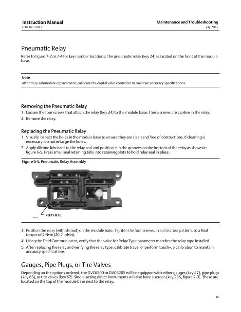
2. Apply silicone lubricant to the relay seal and position it in the grooves on the bottom of the relay as shown in<br />
figure 6‐5. Press small seal retaining tabs into retaining slots to hold relay seal in place.<br />
Figure 6‐5. Pneumatic Relay Assembly<br />
W8074<br />
RELAY SEAL<br />
3. Position the relay (with shroud) on the module base. Tighten the four screws, in a crisscross pattern, to a final<br />
torque of 2 Nm (20.7 lbfin).<br />
4. Using the Field Communicator, verify that the value for Relay Type parameter matches the relay type installed.<br />
5. After replacing the relay and verifying the relay type, calibrate travel or perform touch‐up calibration to maintain<br />
accuracy specifications<br />
Gauges, Pipe Plugs, or Tire <strong>Valve</strong>s<br />
Depending on the options ordered, the <strong>DVC6200</strong> or DVC6205 will be equipped with either gauges (key 47), pipe plugs<br />
(key 66), or tire valves (key 67). Single‐acting direct instruments will also have a screen (key 236, figure 7‐3). These are<br />
located on the top of the module base next to the relay.<br />
63


