1 Spatial Modelling of the Terrestrial Environment - Georeferencial
1 Spatial Modelling of the Terrestrial Environment - Georeferencial
1 Spatial Modelling of the Terrestrial Environment - Georeferencial

You also want an ePaper? Increase the reach of your titles
YUMPU automatically turns print PDFs into web optimized ePapers that Google loves.
124 <strong>Spatial</strong> <strong>Modelling</strong> <strong>of</strong> <strong>the</strong> <strong>Terrestrial</strong> <strong>Environment</strong><br />
Points<br />
5000<br />
4500<br />
4000<br />
3500<br />
3000<br />
2500<br />
2000<br />
1500<br />
1000<br />
500<br />
0<br />
Sparse DEM<br />
r=5; t=2<br />
r=5; t=1<br />
r=5; t=0.5<br />
r=10; t=2<br />
r=10; t=1<br />
points removed<br />
ME (m)<br />
SDE (m)<br />
r=10; t=0.5<br />
r=15; t=2<br />
r=15; t=1<br />
r=15; t=0.5<br />
r=20; t=2<br />
r=20; t=1<br />
r=20; t=0.5<br />
r=25; t=2<br />
r=25; t=1<br />
r=25; t=0.5<br />
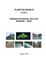
Figure 6.5 The effects <strong>of</strong> different values <strong>of</strong> search radius (r) and tolerance (t) upon <strong>the</strong> number<br />
<strong>of</strong> points, mean error and standard deviation <strong>of</strong> error, using approach 1 for <strong>the</strong> test area shown<br />
in Figure 6.4(a)<br />
and this is reflected in <strong>the</strong> significantly larger number <strong>of</strong> data points removed with <strong>the</strong> 0.5 m<br />
tolerance as compared with 1 m and 2 m tolerances. This emphasizes <strong>the</strong> basic problem<br />
with any type <strong>of</strong> thresholding like this: as tolerance is reduced, smaller reductions in SDE<br />
occur for proportionately larger numbers <strong>of</strong> points lost. There is a tendency towards <strong>the</strong><br />
loss <strong>of</strong> greater amounts <strong>of</strong> potential ‘signal’ as <strong>the</strong> boundary between signal and ‘noise’ is<br />
approached. On <strong>the</strong> basis <strong>of</strong> <strong>the</strong> <strong>the</strong>oretical reasoning above, given <strong>the</strong> relatively low relief<br />
<strong>of</strong> this surface in relation to <strong>the</strong> large amount <strong>of</strong> available data, it was decided to adopt a<br />
radius <strong>of</strong> curvature <strong>of</strong> 20 m with a SD tolerance <strong>of</strong> 0.5 m (Figure 6.4(i)). It is clear that<br />
some, but not all, <strong>of</strong> <strong>the</strong> error in Figure 4(c) has been removed by using a local SD filter.<br />
The main limitation <strong>of</strong> <strong>the</strong> approach above is that it is not as topographically sensitive as it<br />
could be. The SD is locally determined, but <strong>the</strong>re is no variation in tolerance level in relation<br />
to <strong>the</strong> expected standard deviation. As a result, <strong>the</strong>re is a greater probability <strong>of</strong> removal <strong>of</strong><br />
correct points (e.g. along near-vertical channel banks) or retention <strong>of</strong> erroneous points in<br />
areas <strong>of</strong> greater rate <strong>of</strong> topographic change than in those where <strong>the</strong> surface topography is<br />
smoo<strong>the</strong>r. Thus, as a generic method for <strong>the</strong> identification <strong>of</strong> DEM error, <strong>the</strong> success <strong>of</strong> <strong>the</strong><br />
method will be spatially variable in <strong>the</strong> presence <strong>of</strong> spatial variation in natural topographic<br />
variability. It is likely to fail over very rough surfaces where spatial structure in surface<br />
variability is <strong>the</strong> norm. A second method sought to address this problem and is based upon<br />
<strong>the</strong> observation that DEMs collected at coarser resolutions using digital photogrammetry<br />
tend to be smoo<strong>the</strong>r. The method also reflects <strong>the</strong> hierarchical nature <strong>of</strong> <strong>the</strong> stereo-matching<br />
used here. The stereo-matching was area-based, <strong>the</strong> algorithm produces elevation averages<br />
weighted over a given template. Thus, coarser resolution DEMs use a large template in <strong>the</strong><br />
image (i.e., image area) to determine elevation. This tends to increase <strong>the</strong> precision <strong>of</strong> <strong>the</strong><br />
3.5<br />
3.0<br />
2.5<br />
2.0<br />
1.5<br />
1.0<br />
0.5<br />
0.0<br />
metres