1 Spatial Modelling of the Terrestrial Environment - Georeferencial
1 Spatial Modelling of the Terrestrial Environment - Georeferencial
1 Spatial Modelling of the Terrestrial Environment - Georeferencial

Create successful ePaper yourself
Turn your PDF publications into a flip-book with our unique Google optimized e-Paper software.
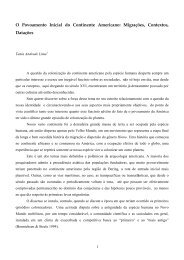
Remotely Sensed Topographic Data for River Channel Research 127<br />
(a)<br />
(b)<br />
Figure 6.8 A visual comparison <strong>of</strong> applying method 1 (search radius = 20 m, tolerance =<br />
0.5 m) and Method 2 (coarse DEM resolution = 5 m, tolerance = 1m)<br />
<strong>of</strong> <strong>the</strong> banding was that it was in <strong>the</strong> areas where <strong>the</strong> individual DEMs overlapped with<br />
one ano<strong>the</strong>r. Initially, after application <strong>of</strong> <strong>the</strong> point post-processing described in section<br />
6.4.1, <strong>the</strong> DEMs were stitched toge<strong>the</strong>r by combining all dry points that had been deemed<br />
acceptable, and <strong>the</strong>n using bilinear interpolation. The effects <strong>of</strong> this could be explored by<br />
comparing <strong>the</strong> surfaces interpolated from <strong>the</strong> individual DEMs where <strong>the</strong>y overlapped. In<br />
this analysis, it is not possible to determine which independent DEM surface is correct: any<br />
discrepancies imply that ei<strong>the</strong>r or both <strong>of</strong> <strong>the</strong> datasets are in error. The results are shown<br />
in Plate 3(a) and in schematic in Plate 3(b). The effect <strong>of</strong> <strong>the</strong> patterns shown in Plate 3(a)<br />
and (b), after bilinear interpolation <strong>of</strong> <strong>the</strong> full dataset, is shown in schematic in Plate 3(c).<br />
Systematic error in both surfaces increases <strong>the</strong> mottling with distance from <strong>the</strong> midpoint<br />
<strong>of</strong> <strong>the</strong> overlap (cf. Plate 3(a)); downstream data points cause more mottling upstream with<br />
distance from <strong>the</strong> centre <strong>of</strong> <strong>the</strong> overlap and upstream data points cause more mottling<br />
downstream with distance from <strong>the</strong> centre <strong>of</strong> <strong>the</strong> overlap. The problem here is that we<br />
do not know which if ei<strong>the</strong>r surface is in error. It is in <strong>the</strong> areas <strong>of</strong> overlap that camera<br />
calibration tends to have greatest effect as <strong>the</strong> overlap areas will be based upon image<br />
pixels that are fur<strong>the</strong>st from <strong>the</strong> principal point <strong>of</strong> symmetry, and where <strong>the</strong> precision <strong>of</strong> <strong>the</strong><br />
camera calibration parameters will be poorest. The geometry <strong>of</strong> stereo-imagery in areas <strong>of</strong><br />
DEM overlap is such that both DEMs will involve image data that is slightly away from<br />
<strong>the</strong> principal point.<br />
6.5 Explanation <strong>of</strong> Errors<br />
Too many <strong>of</strong> <strong>the</strong> attempts to manage error in DEMs are based upon an incomplete understanding<br />
<strong>of</strong> <strong>the</strong> nature <strong>of</strong> that error. A classic example <strong>of</strong> this is <strong>the</strong> application <strong>of</strong> smoothing<br />
functions, such as those based upon a 3 × 3 variance filter, as <strong>the</strong>se simply propagate error<br />
from incorrect points into adjacent points without necessarily removing all <strong>of</strong> <strong>the</strong> error<br />
in <strong>the</strong> incorrect points. One <strong>of</strong> <strong>the</strong> crucial steps in an error analysis is <strong>the</strong> explanation <strong>of</strong><br />
<strong>the</strong> causes <strong>of</strong> that error, so that <strong>the</strong> data collection process can be improved and <strong>the</strong> error