

Electromagnetic Testing Chapter 3- Electromagnetic Testing
Electromagnetic Testing Chapter 3- Electromagnetic Testing
Electromagnetic Testing Chapter 3- Electromagnetic Testing

Create successful ePaper yourself
Turn your PDF publications into a flip-book with our unique Google optimized e-Paper software.
Eddy Current <strong>Testing</strong> at High Temperatures for Controlling Heat<br />
Treatment Processes<br />
1 Introduction<br />
Increasing quality demands have made a reliable quality control getting more and more important for manufacturing and<br />
processing industries. Especially if 100% testing is required, the advantages of the eddy current technique are used by a<br />
wide range of applications to ensure constant quality: eddy current measurements require minimal testing time, offer the<br />
possibility to measure without human intervention and are non-destructive [1]. For heat treating processes, the method is<br />
used in various applications. Aircraft industry for example uses the eddy current technique to measure the conductivity of<br />
heat treated aluminium components to check hardness and tensile strength [2]. To ensure that aluminium plates have been<br />
properly heat treated and exhibit a satisfactory degree of homogeneity, systems are developed that automatically measure<br />
conductivity on the top and the bottom of the plate as sensors scan across [3]. Multi-frequency systems make the control of<br />
ferromagnetic workpieces possible, for example to check material structure or cracks [4-6]. For all of these test procedures,<br />
the measurements are performed after the heat treatment has taken place, as there are no systems, which can be used at<br />
the heat treatment temperatures and atmospheres. Measurements during the treatment would offer much more information<br />
about the process, because not only the final state, but also all the changes during heat treatment could be monitored<br />
continuously. This additional information makes the process saver and can be used to adapt the process more easily, if<br />
changes become necessary. To perform measurements under such difficult conditions at high temperatures the eddy<br />
current technique shows to be the most suitable NDT system because of its easy handling and the simple build-up of the<br />
sensor. The article describes the development of an eddy current measuring system to characterise micro-structural<br />
changes during heat treatment. It can be used at temperatures up to 500°C. The construction of the sensor and the method<br />
of data analysis is illustrated. The system was used to characterise the aging process of the Al Zn Mg Cu alloy EN AW 7075.<br />
The correlation between micro-structural changes and the eddy current signal are discussed.<br />
2 Eddy Current Measurements<br />
2.1 How to detect the heat treatment state with eddy-current testing Eddy currents can be used for material characterisation<br />
because the sensor signal is dependent on two material properties: the electric conductivity and the permeability. These<br />
parameters are often connected strongly to technological relevant quantities, e.g. hardness. Thus the use of eddy currents in<br />
a heat treatment process makes it possible to monitor the quantities characterising the heat treatment state continuously and<br />
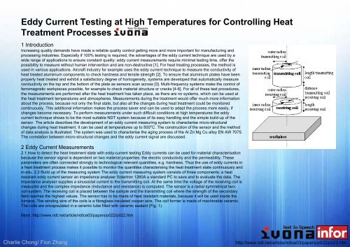
in-situ. 2.2 Build up of the measuring system The eddy current measuring system consists of three components: a heat<br />
resistant eddy current sensor an impedance analyser Solartron 1260A a standard PC to save and to evaluate the data. The<br />
impedance analyser supplies a sinusoidal current to the transmitting coil. At the same time the voltage of the receiving coil is<br />
measured and the complex impedance (inductance and resistance) is computed. The sensor is a radial symmetrical twocoil-system.<br />
The receiving coil is placed between the sample and the transmitting coil where the strength of the secondary<br />
field reaches the highest values. The sensor has to be made of heat resistant materials, because it will be used inside the<br />
furnace. The winding wire of the coils is a fibreglass-insulated cooper wire. The coil former is made of machinable ceramic.<br />
The coils are encapsulated in a ceramic tube filled with ceramic sealant (Fig. 1).<br />
More: http://www.ndt.net/article/ndtce03/papers/p022/p022.htm<br />
Charlie Chong/ Fion Zhang<br />
http://www.ndt.net/article/ndtce03/papers/p022/p022.htm


