MART Vol. II MO/MP - NESA - Civil Air Patrol
MART Vol. II MO/MP - NESA - Civil Air Patrol
MART Vol. II MO/MP - NESA - Civil Air Patrol
You also want an ePaper? Increase the reach of your titles
YUMPU automatically turns print PDFs into web optimized ePapers that Google loves.
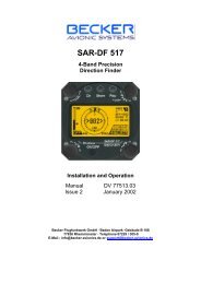
Functional Check - with transmitter and the aircraft on the groundAll features of the DF except the Alarm circuit can be checked using apractice beacon.1. Park the aircraft in the open, away from metal buildings. The transmittershould be at least 50 feet in front of and 15-30 degrees to one side of theaircraft.WARNING: Use of high-power transmitters close to the DF antennae candamage the unit. Damage can occur from a 50-watt transmitter if it is within12 feet of the antennae (3 feet for 5W; 4 1/2 feet for 10W; 15 feet for 80W).The ELT tester should be kept at least 50 feet away from the antennae whenusing to test for operability of the DF.2. Select 121.775 MHz on the DF.3. Rotate the SENSitivity control fully counterclockwise to minimum.4. Set the VOLume control to about the 12 o’clock position.5. Set the Alarm toggle switch off (down).6. Turn on the DF and the transmitter. If necessary, rotate the SENSitivitycontrol clockwise until the signal or the DF buzz is heard.7. The DF needle should point toward the transmitter. Move the transmitter tothe other side of the aircraft and observe the DF needle, which should followthe transmitter. NOTE: On the ground it is normal for the needle to beuncertain about centering with the test transmitter directly fore or aft. The DFis OK if the needle points correctly when the transmitter is on either side ofthe aircraft.8. Move the SENSitivity control clockwise. The strength needle will move(slowly) further to the right.Functional Check - with transmitter and the aircraft in flightPlace the practice beacon as high and clear as possible in open terrain. Fly aboutthree to five miles away at 2000 to 3000 feet AGL. Make several full circles, startingwith no more than a 10° bank-angle. The DF needle should crossover only twiceduring the turn at shallow bank. More than two crossings indicate unsatisfactoryoperation.Pilots and observers should note how the DF performs at steeper bank angles forfuture reference. Note where wing shadows occur, as indicated by decreases in thestrength meter reading and/or audio volume during steep turns; this is a usefulverification of DF indications.Determine the direction to the practice beacon by turning in the direction of DF needledeflection. With the needle centered, follow the DF course inbound and compare it tothe visual heading to the target transmitter. The inbound course and the heading tothe transmitter should agree to +/- 5° (up to +/- 15° error is quite usable). If desired,you can note the error on a placard near the DF receiver.Finally, compare the inbound and the outbound courses using the DG (headingindicator). They should differ by 180°.Course errors of up to 30° are usually due to unsymmetrical installation of theantennas or, on the ground, to nearby reflecting objects (e.g., cars or buildings).Asymmetry usually causes both front and rear courses to be bent toward the sameside of the aircraft and usually toward the source of the problem.Severe errors or one-sided needle indications are usually due to a damaged antennato-switchboxcable or to poor grounding at the antenna or a skin joint nearby. Poorskin-joint contact may well indicate structurally significant corrosion and should beinvestigated by a mechanic.[NOTE: L-Tronics technical support can be reached at 805-967-4859 orwww.ltronics.com]121


