


You also want an ePaper? Increase the reach of your titles
YUMPU automatically turns print PDFs into web optimized ePapers that Google loves.
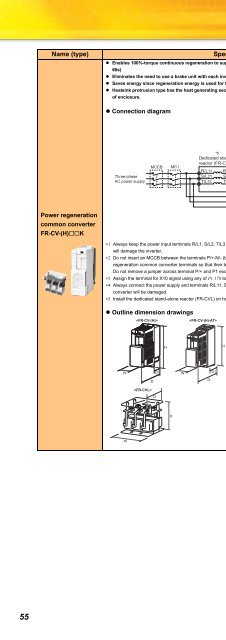
Name (type)Specifications, Structure, etc.• Enables 100%-torque continuous regeneration to support continuous regenerative operation for line control, etc. (Maximum torque 150%60s)• Eliminates the need to use a brake unit with each inverter, reducing total space and total cost.• Saves energy since regeneration energy is used for the other inverters and excess energy is returned to the power supply.• Heatsink protrusion type has the heat generating section outside of the enclosure, and exhaust the converter generated heat to the outsideof enclosure.• Connection diagramR/L1S/L2T/L3*1UVWIMThree-phaseAC power supplyMCCBMC1*5Dedicated stand-alonereactor (FR-CVL)R/L11S/L21T/L31R2/L12S2/L22T2/L32FR-CV type powerregeneration common converterR2/L1S2/L2T2/L3P/L+N/L-P/+N/-Inverter*2Power regenerationcommon converterFR-CV-(H)KR/L11S/L21 *3T/MC1P24SDRDYARDYBRSOSEPCSDMRSRESSD∗1 Always keep the power input terminals R/L1, S/L2, T/L3 open. Incorrect connection will damage the inverter. Opposite polarity of terminals N/-, P/+will damage the inverter.∗2 Do not insert an MCCB between the terminals P/+-N/- (between P/L+-P/+, between N/L--N/-). Connect the inverter terminals (P/+, N/-) and powerregeneration common converter terminals so that their terminal symbols match with each other. Incorrect connection will damage the inverter.Do not remove a jumper across terminal P/+ and P1 except when connecting a DC reactor.∗3 Assign the terminal for X10 signal using any of Pr. 178 to Pr. 184 (input terminal function selection).∗4 Always connect the power supply and terminals R/L11, S/L21, T/MC1. If the inverter is operated without connection, the power regeneration commonconverter will be damaged.∗5 Install the dedicated stand-alone reactor (FR-CVL) on horizontal plane.• Outline dimension drawingsHWD1WD1DDDHWHFR-CV-(H) (Unit mm)Voltage/Capacity W H D D1 Voltage/Capacity W H D D17.5K/11K 90 300 303 10315K 120 300 305 1057.5K/11K/15K 120 300 305 10522K/30K 150 380 322 122 22K/30K 150 380 305 10537K/55K 400 620 250 135 37K/55K 400 620 250 135200VFR-CV-(H)-AT(Unit mm)Voltage/Capacity W H D D1 Voltage/Capacity W H D D17.5K/11K 110 330 315 1157.5K/11K/15K 130 330 320 12015K 130 330 320 12022K/30K 160 410 350 150 22K/30K 160 410 350 150200VFR-CVL(Unit mm)Voltage/Capacity W H D Voltage/Capacity W H D7.5K/11K/15K 165 130 155 7.5K/11K 220 135 20022K 165 140 155 15K 220 135 20530K 215 160 175 22K 220 150 21537K 220 320 200 30K 245 185 22055K 250 335 225 37K 245 230 26555K 290 230 280200V400V400V400V55


