


Create successful ePaper yourself
Turn your PDF publications into a flip-book with our unique Google optimized e-Paper software.
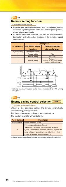
Pr. 59Remote setting functionPr. 59 Remote function selection• If the operation panel is located away from the enclosure, you canuse contact signals to perform continuous variable-speed operation,without using analog signals.• By merely setting this parameter, you can use the acceleration,deceleration and setting clear functions of the motorized speedsetter (FR-FK).DescriptionPr. 59 Setting RH, RM, RL signalfunctionFrequency settingstorage function0 (initial value) Multi-speed setting —1 Remote setting With2 Remote setting Not used3 Remote settingNot used(Turning off STF/STR clearsremotely set frequency)Output frequency (Hz)0Acceleration(RH)Deceleration(RM)Clear (RL)Forward rotation(STF)Power supply*0HzON ON ONONWhen Pr. 59 = 1, 2When Pr. 59 = 3∗ External running frequency (other than multi-speed) or PU runningfrequencyPr. 60Energy saving control selectionPr. 60 Energy saving control selectionWithout a fine parameter setting, the inverter automaticallyperforms energy saving operation.This function is optimum for fan and pump applicationsThis function is valid for V/F control only.Pr. 60 SettingDescription0 (initial value) Normal operation modeOptimum excitation control modeThe optimum excitation control mode is a control9 system which controls excitation current to improve themotor efficiency to maximum and determines outputvoltage as an energy saving system. ∗∗ Output current may slightly increase, since output voltage is controlled.ONWhen Pr. 59 = 2, 3When Pr. 59 = 1ON ON ON ONONONTimeV/FPr. 61 to 63, 292, 293Automatic acceleration/decelerationPr. 61 Reference currentPr. 63 Reference value at decelerationPr. 293 Acceleration/deceleration separate selectionPr. 62 Reference value at accelerationPr. 292 Automatic acceleration/decelerationThe inverter automatically sets appropriate parameters foroperation.• The inverter operates in the same conditions as when appropriatevalues are set in each parameter even if acceleration/decelerationtime and V/F pattern are not set. This operation mode is useful whenyou just want to operate, etc. without fine parameter setting.• If the automatic acceleration/deceleration has been selected,inputting the jog or RT (second function selection) signal during aninverter stop will switch to the normal operation and give priority toJOG operation or second function selection.After automatic acceleration/deceleration operation has beenstarted, none of JOG signal and RT signal are accepted.Pr. 292Setting0(initial valuenormal mode)1(shortestacceleration/decelerationmode)11(shortestacceleration/decelerationmode)7(brake sequencemode 1)8(brake sequencemode 2)Without brakeresistor andbrake unitWith brakeresistor andbrake unitWithmechanicalbrake openingcompletionsignal inputWithoutmechanicalbrake openingcompletionsignal inputOperationAutomaticSettingParameter— —Set when you wantto accelerate/decelerate the motorfor the shortest time.(stall preventionoperation level150%)Operation mode inwhich a mechanicalbrake operationtiming signal forvertical liftapplications isoutput.Pr. 7, Pr. 8• Use Pr. 61 to Pr. 63 to change the reference current for the shortestacceleraiton/deceleration mode and optimum acceleration/deceleration mode.• Calculation of acceleration/deceleration can be performedindividually.This function is made valid in the shortest acceleration/deceleraionmode.Pr. 293 SettingDescription0 (initial value) Both acceleration/deceleration time is calculated.1 Only acceleration time is calculated.2 Only deceleration time is calculated.—33 When setting parameters, refer to the instruction manual (applied) and understand instructions.


