


Create successful ePaper yourself
Turn your PDF publications into a flip-book with our unique Google optimized e-Paper software.
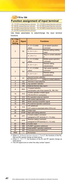
Pr.178 to 184Function assignment of input terminalPr. 178 STF terminal function selectionPr. 180 RL terminal function selectionPr. 182 RH terminal function selectionPr. 184 RES terminal function selectionPr. 179 STR terminal function selectionPr. 181 RM terminal function selectionPr. 183 MRS terminal function selectionUse these parameters to select/change the input terminalfunctions.Pr. 178 toPr. 184 SignalFunctionsSettingPr. 59 = 0 (initial Low-speed operationvalue)command0 RL Pr. 59 = 1, 2 *1Remote setting (settingclear)Pr. 270 = 1 *2Stop-on contact selection0Pr. 59 = 0 (initial Middle-speed operationvalue)command1 RMRemote settingPr. 59 = 1, 2 *1(deceleration)Pr. 59 = 0 (initial High-speed operationvalue)command2 RHRemote settingPr. 59 = 1, 2 *1(acceleration)3 RTSecond function selectionPr. 270 = 1 *2 Stop-on contact selection 14 AU Terminal 4 input selection5 JOG Jog operation selection7 OH External thermal relay input*38 REX15-speed selection(combination with three speeds RL, RM, RH)10 X10Inverter operation enable signal(FR-HC/FR-CV connection)12 X12 PU operation external interlock14 X14 PID control valid terminal15 BRI Brake opening completion signal16 X16 PU-external operation switchover18 X18V/F switchover(V/F control is exercised when X18 is on)24 MRS Output stop25 STOP Start self-holding selection60 STFForward rotation command(assigned to STF terminal (Pr. 178) only)61 STRReverse rotation command(assigned to STR terminal (Pr. 179) only)62 RES Inverter reset65 X65 PU/NET operation switchover66 X66 External/NET operation switchover67 X67 Command source switchover9999 — No function∗1 When Pr. 59 Remote function selection = "1 or 2", the functions of the RL,RM and RH signals change as listed above.∗2 When Pr. 270 = "1", the functions of the RL and RT signals change aslisted above.∗3 The OH signal turns on when the relay contact "opens".Pr.190 to 192Terminal assignment of output terminalPr. 190 RUN terminal function selectionPr. 192 A,B,C terminal function selectionPr. 191 FU terminal function selectionYou can change the functions of the open collector output terminaland relay output terminal.Pr. 190 to Pr. 196SettingPositive NegativeSignalFunctionslogic logic0 100 RUN Inverter running1 101 SU Up to frequency3 103 OL Overload alarm4 104 FU Output frequency detection7 107 RBP Regenerative brake prealarm8 108 THP Electronic thermal relay function prealarm11 111 RY Inverter operation ready12 112 Y12 Output current detection13 113 Y13 Zero current detection14 114 FDN PID lower limit15 115 FUP PID upper limit16 116 RL PID forward/reverse rotation output20 120 BOF Brake opening request25 125 FAN Fan fault output26 126 FIN Heatsink overheat pre-alarm46 146 Y46During deceleration due to instantaneouspower failure (retained until release)47 147 PID During PID control activated64 164 Y64 During retry90 190 Y90 Life alarm91 191 Y91 Fault output 3 (power-off signal)93 193 Y93 Current average value monitor signal95 195 Y95 Maintenance timer signal96 196 REM Remote output98 198 LF Alarm output99 199 ALM Fault output9999 — No functionPr.Pr.Pr.Pr.244232 to 239 Refer to the section about Pr. 4.240 Refer to the section about Pr. 72.241 Refer to the section about Pr. 125.Increase cooling fan lifePr. 244 Cooling fan operation selectionYou can control the operation of the cooling fan (200V class 1.5Kor more) built in the inverter.Pr. 244 Setting01(initial value)DescriptionOperates in power-on status.Cooling fan on/off control invalid(the cooling fan is always on at power on)Cooling fan on/off control validThe fan is always on while the inverter is running.During a stop, the inverter status is monitored andthe fan switches on-off according to the temperature.Pr.245 to 247Slip compensationPr. 245 Rated slipPr. 247 Constant-power range slipcompensation selectionV/FGP MFVCPr. 246 Slip compensation time constantThe inverter output current may be used to assume motor slip tokeep the motor speed constant.41 When setting parameters, refer to the instruction manual (applied) and understand instructions.


