


You also want an ePaper? Increase the reach of your titles
YUMPU automatically turns print PDFs into web optimized ePapers that Google loves.
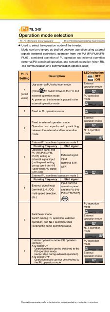
Operation mode selectionPr. 79 Operation mode selection Pr. 340 Communication startup mode selection• Used to select the operation mode of the inverter.Mode can be changed as desired between operation using externalsignals (external operation), operation from the PU (FR-PU04/FR-PU07), combined operation of PU operation and external operation(external/PU combined operation, and network operation (when RS-485 communication or a communication option is used).Pr. 79, 340Pr. 79Setting0(initialvalue)DescriptionUse external/PU switchover mode(press to switch between the PU andexternal operation mode.At power on, the inverter is placed in theexternal operation mode.1 Fixed to PU operation mode23467Fixed to external operation modeOperation can be performed by switchingbetween the external and Net operationmode.Switchover modeSwitch among PU operation, externaloperation, and NET operation whilekeeping the same operating status.LED Indication: OFF: ONExternaloperation modePU operationmodeExternaloperation modeNET operationmodeExternal/PU combined operation mode 1Running frequency Start signalOperation panel andPU (FR-PU04/FR-PU07) setting orexternal signal input(multi-speed setting,across terminals 4-5(valid when AU signalExternal signalinput(terminal STF,STR)turns on)).External/PU combined operation mode 2Running frequency Start signalInput from theExternal signal input operation panel(terminal 2, 4, JOG, and the PU (FRmulti-speedselection, PU04/FR-PU07)etc.)( )PU operationmodeExternal operation mode (PU operationinterlock)X12 signal ONOperation mode can be switched to thePU operation mode.(output stop during external operation)X12 signal OFFOperation mode can not be switched tothe PU operation mode.Externaloperation modeNET operationmodePU operationmodeExternaloperation mode• Specify the operation mode at power on (Pr. 340)• When power is switched on or when power comes back on afterinstantaneous power failure, the inverter can be started up in thenetwork operation mode.After the inverter has started up in the network operation mode,parameter write and operation can be performed from a program.Set this mode for communication operation using the inverter RS-485 communication or communication option.• You can set the operation mode at power on (reset) according tothe Pr. 79 and Pr. 340 settings.Pr. 340SettingPr. 79SettingOperation Mode atPower-on, PowerRestoration,ResetOperation ModeSwitching0(initial As set in Pr. 79.value)0 NET operation modeCan be switched toexternal, PU or NEToperation mode∗11 PU operation modeFixed to PU operationmode2 NET operation modeSwitching between theexternal and NEToperation mode isenabledSwitching to PUoperation mode disabled1 3, 4External/PU combined Operation modeoperation mode switching disabledSwitching among the6 NET operation modeexternal, PU, and NEToperation mode isenabled while running.Can be switched toX12 (MRS) signal ONexternal, PU or NET..NET operation modeoperation mode∗17Fixed to externalX12 (MRS) signal ONoperation mode (forcibly..External operationswitched to externalmodeoperation mode)Switching between the0 NET operation mode PU and Net operationmode is enabled∗21 PU operation modeFixed to PU operationmode2 NET operation modeFixed to NET operationmodeExternal/PUOperation mode3, 4 combined operation10switching disabledmodeSwitching between the6 NET operation modePU and NET operationmode is enabled whilerunning∗2Fixed to external7External operation operation mode (forciblymodeswitched to externaloperation mode)∗1 Operation mode can not be directly changed between the PUoperation mode and network operation mode∗2 Operation mode can be changed between the PU operation mode andnetwork operation mode withsignal.key of the operation panel and X65FeaturesOptionsInstructionsMotorCompatibilityWarrantyInquiryPeripheralDevicesStandardSpecificationsOutlineDimensionDrawingsTerminal ConnectionDiagramTerminal SpecificationExplanationOperation panelParameter unitFR ConfiguratorParameterListExplanationsofParametersProtectiveFunctionsWhen setting parameters, refer to the instruction manual (applied) and understand instructions.36


