


You also want an ePaper? Increase the reach of your titles
YUMPU automatically turns print PDFs into web optimized ePapers that Google loves.
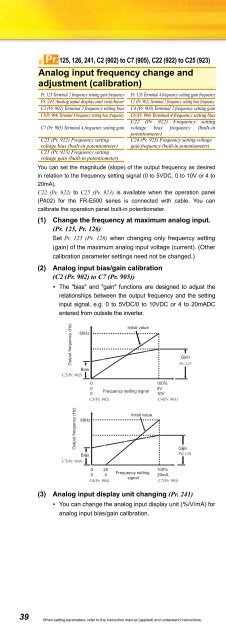
Pr.125, 126, 241, C2 (902) to C7 (905), C22 (922) to C25 (923)Analog input frequency change andadjustment (calibration)Pr. 125 Terminal 2 frequency setting gain frequency Pr. 126 Terminal 4 frequency setting gain frequencyPr. 241 Analog input display unit switchover C2 (Pr. 902) Terminal 2 frequency setting bias frequencyC3 (Pr. 902) Terminal 2 frequency setting bias C4 (Pr. 903) Terminal 2 frequency setting gainC5(Pr. 904) Terminal 4 frequency setting bias frequency C6 (Pr. 904) Terminal 4 frequency setting biasC22 (Pr. 922) Frequency settingC7 (Pr. 905) Terminal 4 frequency setting gain voltage bias frequency (built-inpotentiometer)C23 (Pr. 922) Frequency settingvoltage bias (built-in potentiometer)C24 (Pr. 923) Frequency setting voltagegain frequency (built-in potentiometer)C25 (Pr. 923) Frequency settingvoltage gain (built-in potentiometer)You can set the magnitude (slope) of the output frequency as desiredin relation to the frequency setting signal (0 to 5VDC, 0 to 10V or 4 to20mA).C22 (Pr. 922) to C25 (Pr. 923) is available when the operation panel(PA02) for the FR-E500 series is connected with cable. You cancalibrate the operation panel built-in potentiometer.(1) Change the frequency at maximum analog input.(Pr. 125, Pr. 126)Set Pr. 125 (Pr. 126) when changing only frequency setting(gain) of the maximum analog input voltage (current). (Othercalibration parameter settings need not be changed.)(2) Analog input bias/gain calibration(C2 (Pr. 902) to C7 (Pr. 905))• The "bias" and "gain" functions are designed to adjust therelationships between the output frequency and the settinginput signal, e.g. 0 to 5VDC/0 to 10VDC or 4 to 20mADCentered from outside the inverter.Output frequency (Hz)60HzBiasC2(Pr. 902)Output frequency (Hz)60HzBiasC5(Pr. 904)Initial value0100%0 5VFrequency setting signal010VC3(Pr. 902) C4(Pr. 903)Initial value0 20100%0 4Frequency setting20mAsignalC6(Pr. 904) C7(Pr. 905)GainPr. 125GainPr. 126(3) Analog input display unit changing (Pr. 241)• You can change the analog input display unit (%/V/mA) foranalog input bias/gain calibration.Pr.127 to 134PID control, Dancer controlPr. 127 PID control automatic switchover frequency Pr. 128 PID action selectionPr. 129 PID proportional bandPr. 130 PID integral timePr. 131 PID upper limitPr. 132 PID lower limitPr. 133 PID action set pointPr. 134 PID differential time• The inverter can be used to exercise process control, e.g. flow rate,air volume or pressure.The terminal 2 input signal or parameter setting is used as a setpoint and the terminal 4 input signal used as a feedback value toconstitute a feedback system for PID control.• Pr. 128 = "20, 21" (measured value input)Pr. 133or terminal 2Set point0 to 5VDC(0 to 10VDC)Inverter circuitPID operationManipulated Motorvariable+ - Kp 1+ 1IMTi S+Td S• Performs PID control by feedbacking the position signal of thedancer roller, controlling the dancer roller is in the specified position.Performs dancer control by setting 40 to 43 in Pr. 128 PID actionselection. The main speed command is the speed command of eachoperation mode (external, PU, communication). Performs PIDcontrol by the position detection signal of the dancer roller, then theresult is added to the main speed command.Pr.145Terminal 4Feedback signal (measured value)Kp: Proportionality constant Ti: Integral time S: Operator Td: Differential timeParameter unit display languageselectionPr. 145 PU display language selectionYou can switch the display language of the parameter unit (FR-PU04/FR-PU07) to another.Pr. 145 SettingDescription0 (initial value) Japanese1 English2 German3 French4 Spanish5 Italian6 Swedish7 FinnishPr.146Built-in potentiometer switchingPr. 146 Built-in potentiometer switching4 to 20mADC (0 to 5V, 0 to 10V)When connecting the operation panel (PA02) of the FR-E500series with a cable, use Pr. 146 Built-in potentiometer switching forselecting the operation using the built-in frequency settingpotentiometer, or using [UP/DOWN] key.Pr. 146 SettingDescription0 Built-in frequency setting potentiometer gain1 (initial value) Digital frequency setting by the [UP/DOWN] key.Frequency setting with the built-in frequency setting9999 potentiometer is available when the frequency set by[UP/DOWN] key is "0Hz".39 When setting parameters, refer to the instruction manual (applied) and understand instructions.


