


Create successful ePaper yourself
Turn your PDF publications into a flip-book with our unique Google optimized e-Paper software.
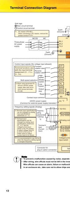
Terminal Connection DiagramSink logicMain circuit terminalControl circuit terminal*1. DC reactor (FR-HEL)When connecting a DC reactor, remove thejumper across P1-P/+Three-phaseAC powersupplyMCCBMCEarth(Ground)JumperR/L1S/L2T/L3P1*1P/+PR*7*6RN/-Brake unit(Option)UVW*6 A brake transistor is not built-in to the 0.1Kand 0.2K.*7 Brake resistor (FR-ABR, MRS, MYS type)Install a thermal relay to prevent anoverheat and burnout of the brake resistor.(The brake resistor can not be connectedto the 0.1K and 0.2K.)MotorIMEarth(Ground)Control input signals (No voltage input allowed)ForwardTerminal functions vary rotation startwith the input terminalReverseassignment (Pr. 178 to rotation startPr. 184)HighspeedMulti-speed selection*2 When using terminals PC-SD as a 24VDC powersupply, take care not toshort across terminalsPC-SD.MiddlespeedLowspeedOutputstopResetContact input common24VDC power supply(Common for external power supply transistor)Frequency setting signals (Analog)3*3 Terminal input specifications Frequencycan be changed by analog settinginput specificationspotentiometer2switchover (Pr. 73).1/2W1kΩ*4 Terminal inputspecifications can bechanged by analog inputspecifications switchover(Pr. 267). Set thevoltage/current inputswitch in the "V" positionto select voltage input (0to 5V/0 to10V) and "I"(initial value) to selectcurrent input (4 to 20mA).*5 It is recommended to use 2W1kΩwhen the frequency setting signalis changed frequently.*51Terminal 4input (+)(Current (-)input)STFSTRRHRMRLMRSRESSDPC *2SOURCE10(+5V)SINK2 0 to 5VDC *3(0 to 10VDC)5(Analog common)4 4 to 20mADC0 to 5VDC0 to 10VDC*4I VVoltage/currentinput switch *4Main circuitControl circuitCBARUNFUSEFMSDPUconnectorUSBconnectorRunningFrequency detectionRelay outputEarth (Ground)Standard control temirnal blockRelay output(Alarm output)Open collector outputOpen collector output commonSink/source commonCalibration resistor*8Terminal functions vary withthe output terminal assignment(Pr. 190 and Pr. 191)+ -Terminal functions varyby Pr. 192 A,B,C terminalfunction selectionIndicator(Frequency meter, etc.)Moving-coil type1mA full-scale*8 It is not necessary whencalibrate the indicator fromthe operation panel.Connector forplug-in option connectionOption connectorNote• To prevent a malfunction caused by noise, separate the signal cables more than 10cm from the power cables.• After wiring, wire offcuts must not be left in the inverter.Wire offcuts can cause an alarm, failure or malfunction. Always keep the inverter clean. When drilling mounting holesin an enclosure etc., take care not to allow chips and other foreign matter to enter the inverter.13


