


Create successful ePaper yourself
Turn your PDF publications into a flip-book with our unique Google optimized e-Paper software.
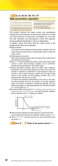
Pr. 22, 23, 48, 66, 156, 157, 277Stall prevention operationPr. 22 Stall prevention operation levelPr. 48 Second stall prevention operation currentPr. 156 Stall prevention operation selectionPr. 277 Stall prevention operation current switchoverPr. 23 Stall prevention operation levelcompensation factor at double speedPr. 66 Stall prevention operationreduction starting frequencyPr. 157 OL signal output timerThis function monitors the output current and automaticallychanges the output frequency to prevent the inverter from comingto an alarm stop due to overcurrent, overvoltage, etc. It can alsolimit stall prevention and fast-response current limit operationduring acceleration/deceleration, driving or regeneration.In addition, torque limit which limits the output torque to thepredetermined value can be selected.• Stall preventionIf the output current exceeds the stall prevention operation level, theoutput frequency of the inverter is automatically varied to reduce theoutput current.• Fast-response current limitIf the current exceeds the limit value, the output of the inverter isshutoff to prevent an overcurrent.• Set in Pr. 22 the percentage of the output current to the rated invertercurrent at which stall prevention operation will be performed.Normally set this parameter to 150% (initial value).• During high-speed operation above the rated motor frequency,acceleration may not be made because the motor current does notincrease. If operation is performed in a high frequency range, thecurrent at motor lockup becomes smaller than the rated outputcurrent of the inverter, and the protective function (OL) is notexecuted even if the motor is at a stop.To improve the operating characteristics of the motor in this case,the stall prevention level can be reduced in the high frequencyrange. This function is effective for performing operation up to thehigh-speed range on a centrifugal separator etc. Normally, set 60Hzin Pr. 66 and 100% in Pr. 23.• By setting "9999" (initial value) in Pr. 23 Stall prevention operation levelcompensation factor at double speed, the stall prevention operationlevel is constant at the Pr. 22 setting up to 400Hz.Pr. 22Stall preventionoperation level (%)Pr. 66When Pr. 23 = 9999Stall prevention operation level aftercompensation factor (Pr. 23) is applied400HzOutput frequency (Hz)• Stall prevention operation and fast response current limit functioncan be restricted according to the operation condition using Pr. 156.• When Pr. 277 = "1" , torque limit can be set. Torque limit level can beset using Pr. 22 .Pr.24 to 27 Refer to the section about Pr. 4.Pr. 29Acceleration/deceleration patternPr. 29 Acceleration/deceleration pattern selectionYou can set the acceleration/deceleration pattern suitable forapplication.• Linear acceleration/deceleration (settingSetting value "0"[Linear acceleration/ "0", initial value)deceleration]For the inverter operation, the outputfrequency is made to change linearly (linearacceleration/deceleration) to prevent themotor and inverter from excessive stress toreach the set frequency during acceleration,deceleration, etc. when frequency changes.(Hz)Output frequency(Hz)Output frequency(Hz) Set frequency (Hz)Output frequencyf1f2fbSelection of regeneration unit• S-pattern acceleration/deceleration A(setting "1")For machine tool spindle applications, etc.Used when acceleration/decelerationmust be made in a short time to a highspeedrange of not lower than Pr. 3 Basefrequency (fb).• S-pattern acceleration/deceleration B(setting "2")For prevention of load shifting inconveyor and other applications.Since acceleration/deceleration is alwaysmade in an S shape from currentfrequency (f2) to target frequency (f1),this function eases shock produced atacceleration/deceleration and is effectivefor load collapse prevention, etc.Pr. 30 Regenerative function selection Pr. 70 Special regenerative brake duty• When making frequent starts/stops, use the optional brake resistorto increase the regeneration capability. (0.4K or more)• Use a power regeneration common converter (FR-CV) for continuousoperation in regeneration status.Use a high efficiency converter (FR-HC) for harmonic suppressionand power factor improvement.Pr. 30Set Value0(initialvalue)TimeSetting value "1"[S-pattern acceleration/deceleration A]TimeSetting value "2"[S-pattern acceleration/deceleration B]Pr. 30, 70TimePr. 70Regeneration UnitSet ValueBrake resistor (MRS, MYS)Brake unit (FR-BU2)∗1Power regeneration common converter (FR-CV)High power factor converter (FR-HC)1 10/6% ∗2 High-duty brake resistor (FR-ABR)High power factor converter (FR-HC)2 — (when an automatic restart afterinstantaneous power failure is selected)∗1 The brake duty varies according to the inverter capacity.∗2 7.5K or less/11K or more29 When setting parameters, refer to the instruction manual (applied) and understand instructions.


