


Create successful ePaper yourself
Turn your PDF publications into a flip-book with our unique Google optimized e-Paper software.
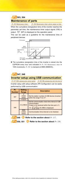
Pr.503, 504Maintenance of partsPr. 503 Maintenance timer Pr. 504 Maintenance timer alarm output set timeWhen the cumulative energization time of the inverter reaches theparameter set time, the maintenance timer output signal (Y95) isoutput. (MT) is displayed on the operation panel.This can be used as a guideline for the maintenance time ofperipheral devices.• The cumulative energization time of the inverter is stored into theE2PROM every hour and indicated in Pr. 503 Maintenance timer in100h increments. Pr. 503 is clamped at 9998 (999800h).Inverter setup using USB communicationPr. 547 USB communication station numberPr. 548 USB communication check time intervalInverter setup with setup software (FR Configurator) can be easilyperformed by USB communication.Pr.Number547548First power9998(999800h)Maintenancetimer(Pr. 503)Pr. 504Y95 signalMT displayPr.547, 548Pr.Pr.SettingRange0(initialvalue)1 to 310 to 999.89999(initialvalue)ONOFFSet "0" in Pr. 503ONDescriptionTimeSet the station number of USB device (inverter)within the range "0 to 31".Set the communication check time interval of USBcommunication.If data is not received within the time set in Pr.548, (E.USB) is displayed.Communication time interval is not checked.549 Refer to the section about Pr. 117.550, 551 Refer to the section about Pr. 338.ONPr.555 to 557Current average value monitor signalPr. 555 Current average timePr. 557 Current average value monitorsignal output reference currentThe average value of the output current during constant speedoperation and the maintenance timer value are output as a pulseto the current average value monitor signal (Y93).The pulse width output to the I/O module of the PLC or the like canbe used as a guideline due to abrasion of machines andelongation of belt and for aged deterioration of devices to know themaintenance time.The current average value monitor signal (Y93) is output as pulsefor 20s as 1 cycle and repeatedly output during constant speedoperation.Y93 signal1) Data output mask timeWhen the speed has changed toconstant from acceleration/deceleration,Y93 signal is not output for Pr. 556 time.2) Start pulseOutput as Hi pulse shape for 1s (fixed)Output current set in Pr. 555 time is averaged3) Output current average value pulseThe averaged current value is output for 0.5 to 9s(10 to 180%) during start bit output.Output current average value (A)Signal output time =5sPr. 557 (A)Pr.Pr.Pr.Pr. 556 Data output mask timeFrom acceleration to constant speed operationOutput frequency1 cycle (20s) Next cycle5) End pulseOutput as low pulseshape for 1 to 16.5s4) Maintenance timer pulseThe maintenance timer value (Pr. 503) isoutput as Hi pulse shape for 2 to 9s(16000h to 72000h)Pr. 503 100hSignal output time =5s40000h563, 564 Refer to the section about Pr. 52.571 Refer to the section about Pr. 13.611 Refer to the section about Pr. 57.TimeFeaturesOptionsInstructionsInquiryWarrantyCompatibilityMotorPeripheralDevicesStandardSpecificationsOutlineDimensionDrawingsTerminal ConnectionDiagramTerminal SpecificationExplanationOperation panelParameter unitFR ConfiguratorParameterListExplanationsofParametersProtectiveFunctionsWhen setting parameters, refer to the instruction manual (applied) and understand instructions.46


