Create successful ePaper yourself
Turn your PDF publications into a flip-book with our unique Google optimized e-Paper software.
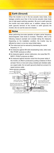
Earth (Ground)When the inverter is run in the low acoustic noise mode, moreleakage currents occur than in the non-low acoustic noise modedue to high-speed switching operation. Be sure to earth (ground)the inverter and motor before use. In addition, always use theearth (ground) terminal of the inverter to earth (ground) theinverter. (Do not use the case and chassis)NoiseNoise reduction examplesFR- BLFInstall filterFR- BSF01on inverter input side.InverterpowersupplyInstall FR-BIF filteron inverter input side.Separate inverter and powerline by more than 30cm (atleast 10cm) from sensor circuit.ControlpowersupplyDo not earth (ground)enclosure directly.EnclosureWhen performing low-noise operation at higher carrier frequency,electromagnetic noise tends to increase. Therefore, refer to thefollowing measure example and consider taking the measures.Depending on the installation condition, the inverter may beaffected by noise in a non-low noise (initial) status.• The noise level can be reduced by decreasing the carrierfrequency (Pr. 72).• As measures against AM radio broadcasting noise, radio noisefilter FR-BIF produces an effect.• As measures against sensor malfunction, line noise filter FR-BSF01, FR-BLF produces an effect.• As measures against induction noise from the power cable ofthe inverter, an effect is produced by putting a distance of 30cm(at least 10cm) or more and using a twisted pair shielded cableas a signal cable. Do not earth (ground) shield but connect it tosignal common cable.FR-BSF01FR-BIFPowersupplyfor sensorDo not earth (ground) control cable.Decreasecarrier frequencyInverterFR-BSF01FR- BLFInstall filterFR- BSF01on inverter output side.IMUse 4-core cable for motorpower cable and use onecable as earth (ground) cable.Use a twisted pair shielded cableSensorDo not earth (ground) shield butconnect it to signal common cable.MotorLeakage currentsCapacitances exist between the inverter I/O cables, other cablesand earth and in the motor, through which a leakage current flows.Since its value depends on the static capacitances, carrierfrequency, etc., low acoustic noise operation at the increasedcarrier frequency of the inverter will increase the leakage current.Therefore, take the following measures. Select the earth leakagecurrent breaker according to its rated sensitivity current,independently of the carrier frequency setting. (Refer to page 58)To-earth (ground) leakage currentsTypeInfluence andmeasuresUndesirablecurrent pathInfluence and Measures• Leakage currents may flow not only into the inverter'sown line but also into the other line through the earth(ground) cable, etc. These leakage currents mayoperate earth (ground) leakage circuit breakers andearth leakage relays unnecessarily.• Countermeasures• If the carrier frequency setting is high, decrease the Pr.72 PWM frequency selection setting.Note that motor noise increases. Select Pr. 240 Soft-PWM operation selection to make the sound inoffensive.• By using earth leakage circuit breakers designed forharmonic and surge suppression in the inverter's ownline and other line, operation can be performed with thecarrier frequency kept high (with low noise).Line leakage currentTypeInfluence and MeasuresInfluence andmeasuresUndesirablecurrent pathPowersupply• This leakage current flows via a static capacitancebetween the inverter output cables.• The external thermal relay may be operatedunnecessarily by the harmonics of the leakage current.• Countermeasures• Use Pr.9 Electronic thermal O/L relay.• If the carrier frequency setting is high, decrease the Pr.72 PWM frequency selection setting.Note that motor noise increases. Select Pr. 240 Soft-PWMoperation selection to make the sound inoffensive.To ensure that the motor is protected against line-tolineleakage currents, it is recommended to use atemperature sensor to directly detect motortemperature.PowersupplyMCCBNV1LeakagebreakerNV2LeakagebreakerMCInverterInverterCCThermal relayCMotorMotorLine-to-line staticcapacitancesLine-to-line leakage currents pathMotorIMFeaturesOptionsInstructionsMotorCompatibilityInquiryWarrantyPeripheralDevicesStandardSpecificationsOutlineDimensionDrawingsTerminal ConnectionDiagramTerminal SpecificationExplanationOperation panelParameter unitFR ConfiguratorParameterListExplanationsofParametersProtectiveFunctions62


