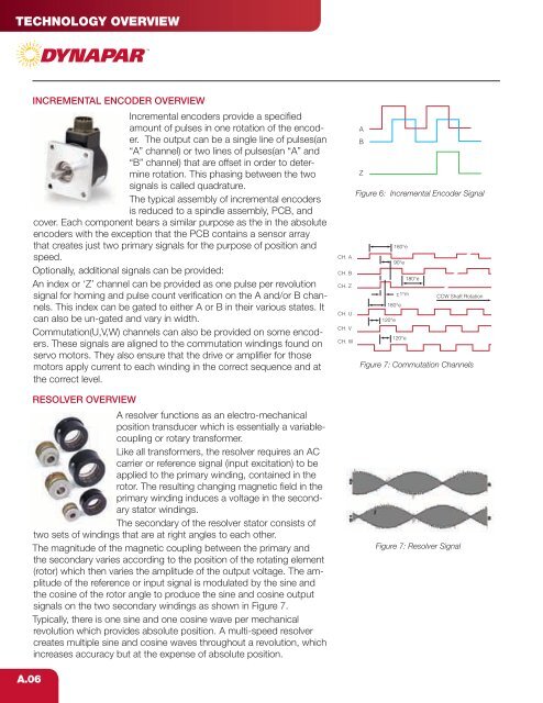
- Page 7: Technology overviewThe cover insure
- Page 11 and 12: EncodEr Mounting configurationsc-fa
- Page 13 and 14: SEALINGEncodEr duty classifications
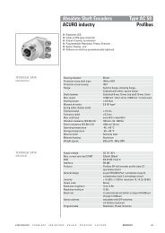
- Page 15 and 16: selection guideAbsoluteShaftedIndus
- Page 17 and 18: Heavy DutyHeavy Duty encoders and r
- Page 19 and 20: Heavy DutyOptical - incremental Opt
- Page 21: yHEAVY DUTYSERIES HD20Code 1: Model
- Page 24 and 25: HEAVY DUTYSERIES HSD25NorthStar br
- Page 26 and 27: HEAVY DUTYSERIES HSD25NorthStar br
- Page 28 and 29: HEAVY DUTYSERIES HSD35Heavy Duty Op
- Page 30 and 31: HEAVY DUTYSERIES HSD35NorthStar br
- Page 32 and 33: HEAVY DUTYSERIES HSD37NorthStar br
- Page 34 and 35: HEAVY DUTYSERIES HSD37NorthStar br
- Page 38 and 39: HEAVY DUTYSERIES HSD38NorthStar br
- Page 40 and 41: HEAVY DUTYSERIES DWD38NorthStar br
- Page 42 and 43: HEAVY DUTYSERIES HSD44NorthStar br
- Page 44 and 45: HEAVY DUTYSERIES EN42NorthStar bra
- Page 46 and 47: HEAVY DUTYSERIES EN44NorthStar bra
- Page 48 and 49: HEAVY DUTYSERIES H56Dynapar brandH
- Page 50 and 51: HEAVY DUTYSERIES X25Dynapar brandF
- Page 52 and 53: HEAVY DUTYSERIES 60Dynapar brandHe
- Page 54 and 55: HEAVY DUTYSERIES 60PDynapar brandH
- Page 56 and 57: HEAVY DUTYSERIES R45Dynapar brandB
- Page 58 and 59:
HEAVY DUTYSERIES SL56NorthStar bra
- Page 60 and 61:
HEAVY DUTYSERIES RL67NorthStar bra
- Page 62 and 63:
HEAVY DUTYSERIES SL85NorthStar bra
- Page 64 and 65:
HEAVY DUTYSERIES SL85NorthStar bra
- Page 66 and 67:
HEAVY DUTYSERIES SL1250NorthStar b
- Page 68 and 69:
HEAVY DUTYSERIES RIM8500NorthStar
- Page 70 and 71:
HEAVY DUTYSERIES RIM 1250NorthStar
- Page 72 and 73:
HEAVY DUTYSERIES RIM 6200NorthStar
- Page 74 and 75:
HEAVY DUTYSERIES HS56NorthStar bra
- Page 76 and 77:
HEAVY DUTYSERIES HS60NorthStar bra
- Page 78 and 79:
HEAVY DUTYSERIES HS85NorthStar bra
- Page 80 and 81:
HEAVY DUTYSERIES AR62/AR63ACURO br
- Page 82 and 83:
HEAVY DUTYSERIES AX70/AX71ACURO br
- Page 84 and 85:
HEAVY DUTYSERIES AX70/AX71ACURO br
- Page 86 and 87:
HEAVY DUTYSERIES R25Harowe brandHe
- Page 88 and 89:
IndustrIal dutyIndustrIal duty Enco
- Page 90 and 91:
IndustrIal dutyoPticAl - incrementA
- Page 92 and 93:
INDUSTRIAL DUTYSERIES 22Dynapar br
- Page 94 and 95:
INDUSTRIAL DUTYSERIES 22Dynapar br
- Page 96 and 97:
INDUSTRIAL DUTYSERIES H20Dynapar b
- Page 98 and 99:
INDUSTRIAL DUTYSERIES H20Dynapar b
- Page 100 and 101:
INDUSTRIAL DUTYSERIES HA25Dynapar
- Page 102 and 103:
INDUSTRIAL DUTYSERIES HA25ELECTRICA
- Page 104 and 105:
INDUSTRIAL DUTYSERIES HR25Dynapar
- Page 106 and 107:
INDUSTRIAL DUTYSERIES HR25Dynapar
- Page 108 and 109:
INDUSTRIAL DUTYSERIES HC25Dynapar
- Page 110 and 111:
INDUSTRIAL DUTYSERIES HC25Dynapar
- Page 112 and 113:
INDUSTRIAL DUTYSERIES H58Dynapar b
- Page 114 and 115:
INDUSTRIAL DUTYSERIES H58Dynapar b
- Page 116 and 117:
INDUSTRIAL DUTYSERIES H42Dynapar b
- Page 118 and 119:
INDUSTRIAL DUTYSERIES HA725Dynapar
- Page 120 and 121:
INDUSTRIAL DUTYSERIES H20 HubshaftD
- Page 122 and 123:
INDUSTRIAL DUTYSERIES H20 HubshaftD
- Page 124 and 125:
INDUSTRIAL DUTYSERIES HS20Dynapar
- Page 126 and 127:
INDUSTRIAL DUTYSERIES HS20Dynapar
- Page 128 and 129:
INDUSTRIAL DUTYSERIES HS35Dynapar
- Page 130 and 131:
INDUSTRIAL DUTYSERIES HS35Dynapar
- Page 132 and 133:
INDUSTRIAL DUTYSERIES HS35RNEW for
- Page 134 and 135:
INDUSTRIAL DUTYSERIES HS35RELECTRIC
- Page 136 and 137:
INDUSTRIAL DUTYSERIES RI80EHengstle
- Page 138 and 139:
INDUSTRIAL DUTYSERIES HA26Dynapar
- Page 140 and 141:
INDUSTRIAL DUTYSERIES HA26Dynapar
- Page 142 and 143:
INDUSTRIAL DUTYSERIES HR26Dynapar
- Page 144 and 145:
INDUSTRIAL DUTYSERIES HR26Dynapar
- Page 146 and 147:
INDUSTRIAL DUTYSERIES HC26Dynapar
- Page 148 and 149:
INDUSTRIAL DUTYSERIES HC26Dynapar
- Page 150 and 151:
INDUSTRIAL DUTYSERIES AC36Absolute
- Page 152 and 153:
INDUSTRIAL DUTYSERIES AI25 DeviceNe
- Page 154 and 155:
INDUSTRIAL DUTYSERIES AI25 CAN Open
- Page 156 and 157:
INDUSTRIAL DUTYSERIES AI25 CANLayer
- Page 158 and 159:
INDUSTRIAL DUTYSERIES AI25 Profibus
- Page 160 and 161:
INDUSTRIAL DUTYSERIES AI25 Interbus
- Page 162 and 163:
INDUSTRIAL DUTYSERIES AI25 BiSSAbso
- Page 164 and 165:
INDUSTRIAL DUTYSERIES AI25 SSIAbsol
- Page 166 and 167:
INDUSTRIAL DUTYSERIES AI25 SSISSI D
- Page 168 and 169:
INDUSTRIAL DUTYSERIES AI25 Parallel
- Page 170 and 171:
INDUSTRIAL DUTYSERIES AI25 Parallel
- Page 172 and 173:
INDUSTRIAL DUTYSERIES AC110Absolute
- Page 174 and 175:
Servo dutyServo Duty FeeDback GuiDe
- Page 176 and 177:
Servo dutyopTICal - absolUTENEWNEWI
- Page 178 and 179:
SERVO DUTYSERIES AD34ACURO brandSi
- Page 180 and 181:
SERVO DUTYSERIES AD35ACURO brandSi
- Page 182 and 183:
SERVO DUTYSERIES AD36ACURO brandSi
- Page 184 and 185:
SERVO DUTYSERIES AD25ACURO brandSi
- Page 186 and 187:
SERVO DUTYSERIES M602 & M832Dynapar
- Page 188 and 189:
SERVO DUTYSERIES M602 & M832byCIRCU
- Page 190 and 191:
SERVO DUTYSERIES LM & LAMORDERING I
- Page 192 and 193:
SERVO DUTYSERIES E9Dynapar brandMi
- Page 194 and 195:
SERVO DUTYSERIES M9Dynapar brandMi
- Page 196 and 197:
SERVO DUTYSERIES M14Dynapar brandM
- Page 198 and 199:
SERVO DUTYSERIES M15Dynapar brandF
- Page 200 and 201:
SERVO DUTYSERIES M53Dynapar brandF
- Page 202 and 203:
SERVO DUTYSERIES F10Dynapar brandF
- Page 204 and 205:
SERVO DUTYSERIES F14Dynapar brandF
- Page 206 and 207:
SERVO DUTYSERIES F15Dynapar brandF
- Page 208 and 209:
SERVO DUTYSERIES F18Dynapar brandF
- Page 210 and 211:
SERVO DUTYSERIES F21Dynapar brandF
- Page 212 and 213:
SERVO DUTYSERIES HC20Dynapar brand
- Page 214 and 215:
SERVO DUTYSERIES 11/R11Harowe bran
- Page 216 and 217:
SERVO DUTYHaroMax Series 15Harowe
- Page 218 and 219:
Light dutyLight Duty EncoDErs guiDE
- Page 220 and 221:
LIGHT DUTYSERIES E12Dynapar brandM
- Page 222 and 223:
LIGHT DUTYSERIES E14Dynapar brandM
- Page 224 and 225:
LIGHT DUTYSERIES E23Dynapar brandM
- Page 226 and 227:
LIGHT DUTYSERIES EC23Dynapar brand
- Page 228 and 229:
LIGHT DUTYSERIES E14HDynapar brand
- Page 230 and 231:
LIGHT DUTYSERIES E14ICDynapar bran
- Page 232 and 233:
Accessories - WheelsNorthStar repla
- Page 234 and 235:
Accessories - cAbles And connectors
- Page 236 and 237:
ACCESSORIESDynapar brandCPL COUPLI
- Page 238 and 239:
ACCESSORIESSERIES FV3Dynapar brand
- Page 240 and 241:
ACCESSORIESPIVOT MOUNTDynapar bran
- Page 242 and 243:
ACCESSORIESQUBE PIVOT MOUNT Dynapar
- Page 244 and 245:
ACCESSORIES5PY ADAPTERDynapar bran
- Page 246 and 247:
ACCESSORIESRIM M100NorthStar brand
- Page 248 and 249:
ACCESSORIESRIM SSWNorthStar brandR
- Page 250:
For additional information, contact


