

WL Circuit Breakers - Siemens
WL Circuit Breakers - Siemens
WL Circuit Breakers - Siemens

Create successful ePaper yourself
Turn your PDF publications into a flip-book with our unique Google optimized e-Paper software.
COM15 (PROFIBUS) / COM16 (MODBUS) Module<br />
<strong>WL</strong> <strong>Circuit</strong> Breaker<br />
PROFIBUS Installation Guide<br />
The COM15 must be assembled and connected to PROFIBUS industry<br />
standards. Of particular importance, is the requirement to ground the<br />
shield of the PROFIBUS cable.<br />
MODBUS Installation Guide<br />
The COM16 must be assembled and connected as described in this<br />
manual. Of particular importance, is the requirement to ground the<br />
shield of the MODBUS R5485 cable.<br />
PROFIBUS/MODBUS Write Protection (DPWriteEnable)<br />
Write access via communications can be blocked either temporarily<br />
or permanently by bridging a jumper across the DP writeenabled<br />
connection.<br />
If this input is not bridged, write access and control is disabled.<br />
The following actions are blocked if the input of the<br />
write-protect function has not been enabled:<br />
• Breaker open/close<br />
• Reset the last trip<br />
• Change the protective parameters<br />
• Change the parameters for the extended protection function<br />
(metering function)<br />
• Change the communication parameters<br />
• Settings of the metering options<br />
• Reset maintenance information (counters)<br />
• Force the digital outputs<br />
The following control functions are available even if the write<br />
protection function has not been enabled:<br />
• Change and set the trigger functions for the<br />
waveform buffer<br />
• Read the content of the waveform buffer<br />
• Change the setpoint parameters<br />
• Set/change the system time<br />
• Change the free texts (comments, system IDs)<br />
• Reset the min./max. values<br />
• Change the unassigned user output<br />
2/9<br />
Graphic<br />
2-2<br />
Graphic<br />
2-3<br />
X8-4<br />
X8-3<br />
X8-2<br />
X8-1<br />
ETU<br />
X8-4<br />
X8-3<br />
X8-2<br />
X8-1<br />
ETU<br />
6<br />
7<br />
8<br />
9<br />
COM16 Close Open<br />
24V DC<br />
K1 K2<br />
6<br />
7<br />
8<br />
9<br />
24V DC<br />
COM16 Close Open<br />
X8-14<br />
X8-13<br />
1 st Shunt<br />
Trip<br />
X8-14<br />
X8-13<br />
1 st Shunt<br />
Trip<br />
X8-8<br />
X8-7<br />
Closing<br />
Coil<br />
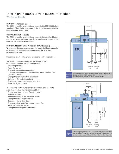
This diagram illustrates how to wire the COM15/COM16 module<br />
if PROFIBUS/MODBUS is to be used to open and close the device.<br />
This diagram only applies to 24V DC control voltage.<br />
X8-8<br />
X8-7<br />
L N<br />
Closing<br />
Coil<br />
Interposing relays are required if a control voltage different than<br />
24V DC is used. If the 1st shunt trip is not used to switch off the<br />
device, use terminals X9.1 and X9.2 to utilize the 2nd shunt trip.<br />
<strong>WL</strong> PROFIBUS/MODBUS Communication and Electronic Accessories


