

WL Circuit Breakers - Siemens
WL Circuit Breakers - Siemens
WL Circuit Breakers - Siemens

Create successful ePaper yourself
Turn your PDF publications into a flip-book with our unique Google optimized e-Paper software.
External Power Consumption<br />
<strong>WL</strong> <strong>Circuit</strong> Breaker<br />
<strong>WL</strong> <strong>Circuit</strong> <strong>Breakers</strong> with CubicleBUS<br />
are designed to provide internal and<br />
external communication when the<br />
main contacts are open. It is therefore<br />
necessary to connect an external<br />
power supply.<br />
2/33<br />
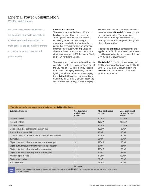
Table to calculate the power consumption of an CubicleBUS System<br />
CubicleBUS Modules # of CubicleBUS Max. continuous Max. peak inrush<br />
modules per current current for each<br />
breaker module<br />
Trip unit ETU745 1 120mA 2000mA<br />
Trip unit ETU755 1 120mA 2000mA<br />
Trip unit ETU776 1 170mA 2000mA<br />
Metering Function or Metering Function Plus 1 120mA 120mA<br />
Breaker Status Sensor BSS 1 40mA 110mA<br />
COM15/COM16 PROFIBUS/MODBUS communication module 1 125mA 280mA<br />
ZSI module 1 50mA 125mA<br />
Digital output module with rotary switch, relay output 1 - 2 180mA 125mA<br />
Digital output module with rotary switch, opto coupler 1 - 2 50mA 125mA<br />
Digital output module configurable, relay output 1 180mA 125mA<br />
Digital output module configurable, opto coupler 1 50mA 125mA<br />
Analog output module 1 - 2 110mA 800mA<br />
Digital input module 1 - 2 30mA 125mA<br />
BDA or BDA Plus 1<br />
Summary<br />
250mA 350mA<br />
Table<br />
2-23<br />
General Information<br />
The current sensing devices of <strong>WL</strong> <strong>Circuit</strong><br />
<strong>Breakers</strong> consist of two components.<br />
The Rogowski coils deliver the current<br />
measuring values, and the energy<br />
converters provide the trip units with<br />
power. For breakers without an additional<br />
external power supply, the trip units are<br />
already activated and monitor the current<br />
at minimum values of 80A for Frame Size II,<br />
and 150A for Frame Size III.<br />
The current from the sensors is sufficient to<br />
not only activate the protective functions of<br />
the ETU745 or ETU748 trip units, but also<br />
to activate the display. However, the backlighting<br />
requires an external power supply.<br />
If the CubicleBUS has been connected to a<br />
UL Listed 24V DC class 2 power supply, the<br />
display is fed with energy from this supply.<br />
To find a suitable external power supply for the <strong>WL</strong> <strong>Circuit</strong> Breaker with CubicleBUS the continuous current and the peak inrush current<br />
must be observed.<br />
The display of the ETU776 only functions<br />
when an external CubicleBUS power supply<br />
has been connected. The protective<br />
functions are fully operational when<br />
primary current is flowing even though the<br />
display is not active.<br />
If additional CubicleBUS components are<br />
applied on a <strong>WL</strong> <strong>Circuit</strong> Breaker, the breaker<br />
must be connected to an external UL Listed<br />
24V DC class 2 power supply.<br />
The CubicleBUS consists of four wires, two<br />
for the communications and two for the UL<br />
Listed 24V DC class 2 power supply. The<br />
CubicleBUS is connected to the external<br />
terminal X8.1 to X8.2.<br />
<strong>WL</strong> PROFIBUS/MODBUS Communication and Electronic Accessories


