

WL Circuit Breakers - Siemens
WL Circuit Breakers - Siemens
WL Circuit Breakers - Siemens

You also want an ePaper? Increase the reach of your titles
YUMPU automatically turns print PDFs into web optimized ePapers that Google loves.
Functions/Parameters for Communications<br />
<strong>WL</strong> <strong>Circuit</strong> Breaker<br />
The <strong>WL</strong> breaker can help facilitate your<br />
load management scheme and integrate<br />
it into your communication network<br />
directly from the breakers trip unit.<br />
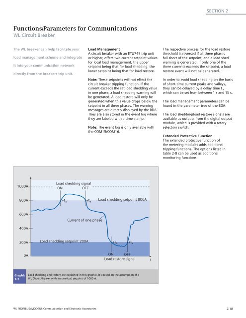
1000A<br />
800A<br />
600A<br />
400A<br />
200A<br />
Graphic<br />
2-5<br />
0A<br />
Load shedding signal<br />
ON OFF<br />
t x<br />
Current of one phase<br />
Load shedding setpoint 200A<br />
t x<br />
Load shedding setpoint 800A<br />
t x<br />
t x<br />
ON OFF<br />
Load restore signal<br />
Load shedding and restore are explained in this graphic. It’s based on the assumption of a<br />
<strong>WL</strong> <strong>Circuit</strong> Breaker with an overload setpoint of 1000 A.<br />
<strong>WL</strong> PROFIBUS/MODBUS Communication and Electronic Accessories<br />
Load Management<br />
A circuit breaker with an ETU745 trip unit<br />
or higher, offers two current setpoint values<br />
for local load management, the upper<br />
setpoint being that for load shedding, the<br />
lower setpoint being that for load restore.<br />
Note: These setpoints will not effect the<br />
circuit breaker tripping function. If the<br />
current exceeds the set load shedding value<br />
in one phase, a load shedding warning will<br />
be generated. A load restore will only be<br />
generated when this value drops below the<br />
setpoint in all three phases. The warning<br />
messages are directly displayed by the BDA.<br />
They are also stored in the event log where<br />
they are labeled with a time stamp.<br />
Note: The event log is only available with<br />
the COM15/COM16.<br />
t<br />
SECTION 2<br />
The respective process for the load restore<br />
threshold is reversed if all three phases<br />
fall short of the setpoint, and a load shed<br />
warning is generated. If only one of the<br />
three currents exceeds the setpoint, a load<br />
restore event will not be generated.<br />
In order to avoid load shedding on the basis<br />
of short-time current peaks and valleys,<br />
they can be delayed by a delay time t x<br />
which can be set from between 1 s and 15 s.<br />
The load management parameters can be<br />
found in the parameter tree of the BDA.<br />
The load shedding/load restore signals are<br />
available as outputs from the digital output<br />
module, which is provided with a rotary<br />
selection switch.<br />
Extended Protective Function<br />
The extended protective function of<br />
the metering modules adds additional<br />
tripping functions. The options listed in<br />
table 2-8 can be used as additional<br />
monitoring functions.<br />
2/18


