

WL Circuit Breakers - Siemens
WL Circuit Breakers - Siemens
WL Circuit Breakers - Siemens

You also want an ePaper? Increase the reach of your titles
YUMPU automatically turns print PDFs into web optimized ePapers that Google loves.
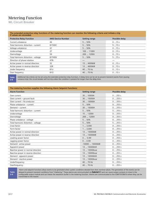
Metering Function<br />
<strong>WL</strong> <strong>Circuit</strong> Breaker<br />
The extended protective relay functions of the metering function can monitor the following criteria and initiate a trip<br />
if values are exceeded.<br />
Protective Relay Function ANSI Device Number Setting range Possible delay<br />
Current unbalance 46 5 ... 50% 0 ...15 s<br />
Total harmonic distortion - current 81THDC 5 ... 50% 5 ...15 s<br />
Voltage unbalance 47 5 ... 50% 0 ...15 s<br />
Undervoltage 27 100 ... 1100V 0 ...15 s<br />
Overvoltage 59 200 ... 1200V 0 ...15 s<br />
Total harmonic distortion - voltage 81THDV 5 ... 50% 5 ...15 s<br />
Direction of phase rotation 47N — —<br />
Active power in normal direction 32 13 ... 4000kW 0 ...15 s<br />
Active power in reverse direction 32R 13 ... 4000kW 0 ...15 s<br />
Under frequency 81U 40 ... 70 Hz 0 ...15 s<br />
Over frequency 81O 40 ... 70 Hz 0 ...15 s<br />
Table<br />
2-8<br />
Table<br />
2-9<br />
2/17<br />
Additional trip criteria can be set using the extended protective relay functions. A delay time can be set to prevent transient events from causing<br />
nuisance trips: the circuit breaker will not trip unless the condition is present for longer than the delay time.<br />
The metering function supplies the following Alarm Setpoint Functions:<br />
Alarm Function Setting range Possible delay<br />
Over current 30 ... 10000A 0 ... 255 s<br />
Over current – ground fault 30 ... 10000A 0 ... 255 s<br />
Over current – N-conductor 30 ... 10000A 0 ... 255 s<br />
Phase unbalance – current 5 ... 50% 0 ... 255 s<br />
Demand – current 30 ... 10000A 0 ... 255 s<br />
Total harmonic distortion - current 5 ... 50% 5 ... 255 s<br />
Undervoltage 15 ... 1200V 0 ... 255 s<br />
Overvoltage 200 ... 1200V 0 ... 255 s<br />
Phase unbalance - voltage 5 ... 50% 0 ... 255 s<br />
Total harmonic distortion - voltage 5 ... 50% 5 ... 255 s<br />
Crest factor 1 ... 3,000 0 ... 255 s<br />
Form factor 1 ... 3,000 0 ... 255 s<br />
Active power in normal direction 13 ... 10000kW 0 ... 255 s<br />
Active power in reverse direction 13 ... 10000kW 0 ... 255 s<br />
Leading power factor 0 ... -0.99 0 ... 255 s<br />
Lagging power factor 0 ... 0.99 0 ... 255 s<br />
Demand - active power -10000 ... 10000kW 0 ... 255 s<br />
Apparent power 13 ... 10000kVA 0 ... 255 s<br />
Reactive power in normal direction 13 ... 10000kvar 0 ... 255 s<br />
Reactive power in reverse direction 13 ... 10000kvar 0 ... 255 s<br />
Demand - apparent power 13 ... 10000kVA 0 ... 255 s<br />
Demand - reactive power 13 ... 10000kvar 0 ... 255 s<br />
Underfrequency 40 ... 70 Hz 0 ... 255 s<br />
Overfrequency 40 ... 70 Hz 0 ... 255 s<br />
Alarm and setpoint functions allow events to be generated when system conditions deviate from their nominal values. The generation of the events can be<br />
delayed to prevent transient conditions from “chattering.” These alarms are communicated via CubicleBUS and can cause output contacts to close in the<br />
configurable output module and can freeze the waveform buffer in the metering function. Alarms are communicated to the COM15/COM16 where they can be<br />
transmitted to the master.<br />
<strong>WL</strong> PROFIBUS/MODBUS Communication and Electronic Accessories


