

WL Circuit Breakers - Siemens
WL Circuit Breakers - Siemens
WL Circuit Breakers - Siemens

You also want an ePaper? Increase the reach of your titles
YUMPU automatically turns print PDFs into web optimized ePapers that Google loves.
External CubicleBUS Modules<br />
<strong>WL</strong> <strong>Circuit</strong> Breaker<br />
Digital Output Module with<br />
Rotary Switch<br />
The digital output module can be used to<br />
output six events. These events can be<br />
warnings or trips and can be used for<br />
external annunciation or control.<br />
The load shedding and load restoring<br />
signals can enable a load to be switched<br />
ON or OFF automatically.<br />
The digital output module is available in<br />
two versions. The “optocoupler” version<br />
features solid state outputs. The current<br />
carrying capacity of this output is 150mA,<br />
and the nominal voltage is 24V DC. Only<br />
DC voltage can be switched. The “relay”<br />
version, uses a relay contact with a<br />
maximum load of 12A. Voltages of up<br />
250V AC/DC are possible. The relay contacts<br />
are isolated.<br />
The module is configured using a rotary<br />
switch, which not only selects one of the<br />
two output module versions, but also sets<br />
the appropriate delay time.<br />
2/25<br />
Selector Switch Position to the Left<br />
If the rotary switch is positioned to the left,<br />
outputs 1 through 6 are assigned the<br />
following events:<br />
• Output 1: Long-time trip (L)<br />
• Output 2: Short-time trip (S)<br />
• Output 3: Instantaneous trip (I)<br />
• Output 4: Ground fault trip (G)<br />
• Output 5: Ground fault alarm signal<br />
• Output 6: Trip as a result of overload in<br />
the neutral conductor (N)<br />
Selector Switch Position to the Right<br />
If the rotary switch is positioned to the<br />
right, outputs 1 through 6 are assigned<br />
the following events:<br />
• Output 1: Leading overload trip signal<br />
(delay time 0s)<br />
• Output 2: Trip unit error (ETU)<br />
• Output 3: Load shedding<br />
• Output 4: Load restoring<br />
• Output 5: Temperature alarm<br />
• Output 6: Current phase unbalance<br />
Technical data for the digital output module with a rotary selection switch<br />
Operating voltage min./max. 19.2V / 28.8V<br />
Operating current min./max. optocoupler 29mA / 63mA<br />
Operating current min./max. relay 29mA / 250mA<br />
No. of isolated channels per digital output module 6<br />
Max. current rating for optocoupler output with 24V DC 100mA<br />
Max. current rating for relay output with 24V DC / 250 V AC / 250V DC 5A / 5A / 0.25A<br />
Max. no. of digital output modules on one CubicleBUS 2<br />
Power loss min./max. 0.74W / 5.4W<br />
Dimensions W/H/D 70mm / 86mm /95mm<br />
Weight (optocoupler/relay) 0.223 kg / 0.321 kg<br />
Temperature range -20°C / 60°C<br />
Table<br />
2-16<br />
This table provides technical data for the digital output module with rotary switch on the CubicleBUS.<br />
Delay Time<br />
The rotary switch can also be used<br />
to set an additional delay time. Available<br />
times are 0, 0.2 s, 0.5 s, 1 s, and 2 s. These<br />
can be used, for example, to suppress<br />
events that only last a short time and not<br />
output them until they have been present<br />
for a long period (e.g. phase unbalance).<br />
Irrespective of the delay time that has been<br />
set, the signal for the leading overload trip,<br />
which can be used to switch off and protect<br />
connected frequency converters, is<br />
always instantaneous.<br />
A maximum of two digital output modules<br />
with rotary switches can be operated<br />
simultaneously on one <strong>WL</strong> <strong>Circuit</strong> Breaker,<br />
otherwise erroneous outputs may occur.<br />
They must be configured opposite each<br />
other. One in the operating mode with<br />
the switch position to the left and one<br />
with the switch position to the right.<br />
The LEDs display the current state of the 6<br />
outputs. If the LED is OFF, corresponding<br />
output is OFF. If the LED is yellow, the<br />
output is ON.<br />
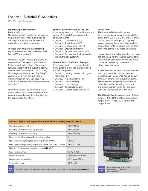
Figure<br />
2-12<br />
Switch positioned to left / right<br />
selects events in dark-gray /<br />
light-gray fields.<br />
<strong>WL</strong> PROFIBUS/MODBUS Communication and Electronic Accessories


