

WL Circuit Breakers - Siemens
WL Circuit Breakers - Siemens
WL Circuit Breakers - Siemens

You also want an ePaper? Increase the reach of your titles
YUMPU automatically turns print PDFs into web optimized ePapers that Google loves.
Functions/Parameters for Communications<br />
<strong>WL</strong> <strong>Circuit</strong> Breaker<br />
Setpoints<br />
In addition to the load management option<br />
(load shedding/load restore), the metering<br />
module offers an option for automatic<br />
monitoring of operating data and the<br />
generation of an alarm.<br />
Two setpoints can be defined (e.g., for<br />
overvoltage). With the lower setpoint, an<br />
alarm can be generated via the setpoint<br />
value (e.g. > 480V), whereas, with a<br />
voltage increase, a tripping event (e.g. ><br />
528V) can be generated.<br />
Minimum for Communicated Currents<br />
In order to avoid the detection, display<br />
and communication of very low currents<br />
generated by system noise, even with the<br />
circuit breaker in the disconnect position,<br />
the “Minimum for Communicated Currents”<br />
parameter offers the option of setting all<br />
detected current values smaller than this<br />
parameter to zero. The factory setting is<br />
50A. This means that all values smaller<br />
than 50A are displayed as “0” on the<br />
display, interpreted as “0” for internal<br />
calculations (power) and also transmitted<br />
as “0” via the communications. If this<br />
parameter is changed to “0”, this function<br />
is deactivated and all detected current<br />
measuring values will be directly used.<br />
2/19<br />
The parameter can be found in the parameter<br />
tree of the BDA.<br />
Normal Positive Power Flow Direction<br />
The current direction of the energy “flow”<br />
and the question, “How much energy has,<br />
up to now, flowed in both directions?” is of<br />
particular interest for tie breaker applications.<br />
For a determination, it is important to<br />
define a “normal direction.” This direction<br />
can either be “from top to bottom” or “from<br />
bottom to top.”The measured real power is<br />
either assigned a positive polarity (in<br />
normal direction) or a negative polarity<br />
(opposite of normal direction). In contrast,<br />
the measured currents are always assigned<br />
a positive polarity.<br />
With energy, the transmitted energy values<br />
are incorporated in two counters, real<br />
energy and real energy opposite to normal<br />
direction. The two energy counters are not<br />
assigned a polarity.<br />
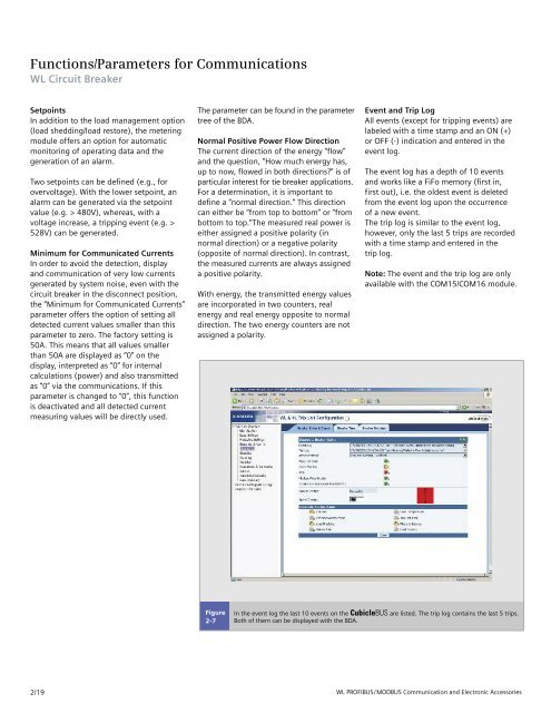
Figure<br />
2-7<br />
Event and Trip Log<br />
All events (except for tripping events) are<br />
labeled with a time stamp and an ON (+)<br />
or OFF (-) indication and entered in the<br />
event log.<br />
The event log has a depth of 10 events<br />
and works like a FiFo memory (first in,<br />
first out), i.e. the oldest event is deleted<br />
from the event log upon the occurrence<br />
of a new event.<br />
The trip log is similar to the event log,<br />
however, only the last 5 trips are recorded<br />
with a time stamp and entered in the<br />
trip log.<br />
Note: The event and the trip log are only<br />
available with the COM15/COM16 module.<br />
In the event log the last 10 events on the CubicleBUS are listed. The trip log contains the last 5 trips.<br />
Both of them can be displayed with the BDA.<br />
<strong>WL</strong> PROFIBUS/MODBUS Communication and Electronic Accessories


