

WL Circuit Breakers - Siemens
WL Circuit Breakers - Siemens
WL Circuit Breakers - Siemens

Create successful ePaper yourself
Turn your PDF publications into a flip-book with our unique Google optimized e-Paper software.
Diagnostic<br />
<strong>WL</strong> <strong>Circuit</strong> Breaker<br />
Control Bytes<br />
The three basic types differ with regard to the<br />
quantity and content of the data reported<br />
from the circuit breaker to the class 1<br />
master (e.g. PLC) with each Data_Exchange.<br />
By standard convention, this data refers<br />
to input data from the point of view of<br />
the PLC.<br />
The output data of the class 1 master<br />
is identical in all three basic types. The<br />
control bytes to the circuit breaker are<br />
always two bytes long. These control bytes<br />
can be used to switch the circuit breaker<br />
(open/close), acknowledge trips, and reset<br />
memory contents.<br />
It is sufficient to set the bits for all the<br />
controllers to between 0.5 and 5 seconds<br />
because setting the output is edge triggered.<br />
The control bits must then be reset to<br />
prevent any unwanted actions from<br />
subsequently being triggered.<br />
PROFIBUS Write Protection<br />
(DPWriteEnable)<br />
Important write accesses can be blocked<br />
from the PROFIBUS-DP. For this purpose,<br />
a hardware input is available on the<br />
COM15 module.<br />
If this input is not bridged (active release),<br />
write access is not possible, with noted<br />
exceptions for remote diagnostics. For<br />
additional information on the precise<br />
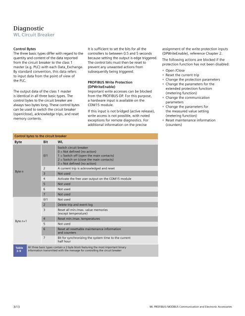
Control bytes to the circuit breaker<br />
Byte Bit <strong>WL</strong><br />
Switch circuit breaker<br />
0 = Not defined (no action)<br />
0/1 1 = Switch off (open the main contacts)<br />
2 = Switch on (close the main contacts)<br />
3 = Not defined (no action)<br />
Byte n<br />
2<br />
3<br />
A current trip is acknowledged and reset<br />
Not used<br />
4 Activate the free user output on the COM15 module<br />
5 Not used<br />
6 Not used<br />
7 Not used<br />
0/1 Not used<br />
2 Delete trip and event log<br />
3 Reset all min./max. value memories<br />
(except temperature)<br />
Byte n+1<br />
4<br />
5<br />
Reset min./max. temperatures<br />
Not used<br />
6 Reset all resettable maintenance information<br />
and counters<br />
7 Bit for synchronizing the system time to the current<br />
half hour<br />
Table<br />
3-9<br />
All three basic types contain a 2-byte block featuring the most important binary<br />
information transmitted with the message for controlling the circuit breaker<br />
assignment of the write protection inputs<br />
(DPWriteEnable), reference Chapter 2.<br />
The following actions are blocked if the<br />
protection function has not been disabled:<br />
• Open /Close<br />
• Reset the current trip<br />
• Change the protection parameters<br />
• Change the parameters for the<br />
extended protection function<br />
(metering function)<br />
• Change the communication<br />
parameters<br />
• Change the parameters for<br />
the measured value setting<br />
(metering function)<br />
• Reset maintenance information<br />
(counters)<br />
3/13 <strong>WL</strong> PROFIBUS/MODBUS Communication and Electronic Accessories


