

WL Circuit Breakers - Siemens
WL Circuit Breakers - Siemens
WL Circuit Breakers - Siemens

Create successful ePaper yourself
Turn your PDF publications into a flip-book with our unique Google optimized e-Paper software.
External CubicleBUS Modules<br />
<strong>WL</strong> <strong>Circuit</strong> Breaker<br />
Testing the Digital Input and<br />
Output Modules<br />
The test should be performed prior to any<br />
commissioning work to determine whether<br />
the circuit breaker and its components<br />
function properly.<br />
The test mode can be used to check that<br />
the CubicleBUS modules function properly.<br />
A distinction must be made between the<br />
individual modules.<br />
Pressing the “Test” key on the CubicleBUS<br />
module starts the test mode, and all the<br />
inputs, outputs, and associated LEDs are<br />
deactivated. The DEVICE LED changes from<br />
green to yellow.<br />
Pressing the “Test” key several times<br />
in quick succession then switches the<br />
corresponding input or output ON and<br />
OFF alternately.<br />
With the input module, the input signals<br />
are also transmitted via the CubicleBUS and<br />
via the COM15/COM16 if connected.<br />
With the digital output modules, the<br />
associated outputs are also switched,<br />
thereby enabling the system to be checked.<br />
The test mode of the analog output module<br />
and the ZSI module is described in the<br />
section for the appropriate module.<br />
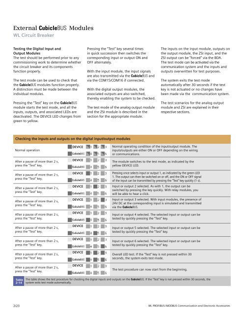
Checking the inputs and outputs on the digital input/output modules<br />
Normal operation<br />
After a pause of more than 2 s,<br />
press the "Test" key.<br />
After a pause of more than 2 s,<br />
press the "Test" key.<br />
After a pause of more than 2 s,<br />
press the "Test" key.<br />
After a pause of more than 2 s,<br />
press the "Test" key.<br />
After a pause of more than 2 s,<br />
press the "Test" key.<br />
After a pause of more than 2 s,<br />
press the "Test" key.<br />
After a pause of more than 2 s,<br />
press the "Test" key.<br />
After a pause of more than 2 s,<br />
press the "Test" key.<br />
After a pause of more than 2 s,<br />
press the "Test" key.<br />
Table<br />
2-14<br />
2/23<br />
DEVICE<br />
DEVICE<br />
DEVICE<br />
DEVICE<br />
DEVICE<br />
DEVICE<br />
DEVICE<br />
DEVICE<br />
DEVICE<br />
DEVICE<br />
The inputs on the input module, outputs on<br />
the output module, the ZSI input, and the<br />
ZSI output can be ”forced‘’ via the BDA.<br />
The test mode can be activated via the<br />
communication system and the inputs and<br />
outputs overwritten for test purposes.<br />
The system exits the test mode<br />
automatically after 30 seconds if the test<br />
key is not actuated or no changes have<br />
been made via the communication system.<br />
The test scenarios for the analog output<br />
module and ZSI are explained in their<br />
respective sections.<br />
Normal operating condition of the input/output module. The<br />
inputs/outputs are either ON or OFF depending on the wiring<br />
or communications.<br />
The module switches to the test mode, as indicated by the<br />
yellow DEVICE LED.<br />
Pressing once selects input or output 1, as indicated by the green LED<br />
1. The output can then be switched on or off, and the ON or OFF signal<br />
of the input can be transmitted by pressing the "Test" key quickly (1 s).<br />
Input or output 2 selected. As with 1, the output can be<br />
switched by pressing the key quickly. With relay modules, you<br />
will be able to hear a click.<br />
Input or output 3 selected. With input modules, the presence of<br />
24V DC at the corresponding input is simulated and transmitted<br />
via the CubicleBUS.<br />
Input or output 4 selected. The selected input or output can be<br />
tested by quickly pressing the "Test" key.<br />
Input or output 5 selected. The selected input or output can be<br />
tested by quickly pressing the "Test" key.<br />
Input or output 6 selected. The selected input or output can be<br />
tested by quickly pressing the "Test" key.<br />
Overall LED test. If the "Test" key is not pressed within 30<br />
seconds, the system exits test mode.<br />
The test procedure can now start from the beginning.<br />
The table shows the test procedure for checking the digital inputs and outputs on the CubicleBUS. If the “Test” key is not pressed within 30 seconds, the<br />
system exits test mode automatically.<br />
<strong>WL</strong> PROFIBUS/MODBUS Communication and Electronic Accessories


