

WL Circuit Breakers - Siemens
WL Circuit Breakers - Siemens
WL Circuit Breakers - Siemens

You also want an ePaper? Increase the reach of your titles
YUMPU automatically turns print PDFs into web optimized ePapers that Google loves.
External CubicleBUS Modules<br />
<strong>WL</strong> <strong>Circuit</strong> Breaker<br />
A01: Network frequency<br />
A02: Average value of the phase-to-phase<br />
voltages<br />
A03: Total active power<br />
A04: Average value of the power factors<br />
The scale for displaying the frequency must<br />
range from 45Hz to 65Hz. This enables the<br />
standard frequencies in countries where IEC<br />
and UL standards apply to be displayed.<br />
Example: 45Hz = 0 V/4mA and 65Hz =<br />
10V/20mA.<br />
The scalings of the other measured values<br />
can be read in the appropriate switch<br />
positions.<br />
Switch Position “cosϕ”<br />
The following measured values are output<br />
in switch position “cosΦ”:<br />
A01: Power factor cosϕL1<br />
A02: Power factor cosϕL2<br />
A03: Power factor cosϕL3<br />
A04: Phase unbalance – current (%)<br />
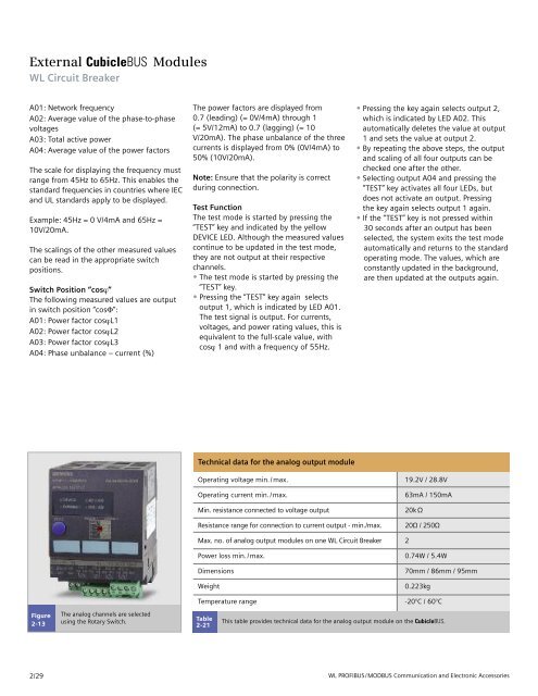
Figure<br />
2-13<br />
2/29<br />
The analog channels are selected<br />
using the Rotary Switch.<br />
The power factors are displayed from<br />
0.7 (leading) (= 0V/4mA) through 1<br />
(= 5V/12mA) to 0.7 (lagging) (= 10<br />
V/20mA). The phase unbalance of the three<br />
currents is displayed from 0% (0V/4mA) to<br />
50% (10V/20mA).<br />
Note: Ensure that the polarity is correct<br />
during connection.<br />
Test Function<br />
The test mode is started by pressing the<br />
“TEST” key and indicated by the yellow<br />
DEVICE LED. Although the measured values<br />
continue to be updated in the test mode,<br />
they are not output at their respective<br />
channels.<br />
• The test mode is started by pressing the<br />
“TEST” key.<br />
• Pressing the “TEST” key again selects<br />
output 1, which is indicated by LED A01.<br />
The test signal is output. For currents,<br />
voltages, and power rating values, this is<br />
equivalent to the full-scale value, with<br />
cosϕ 1 and with a frequency of 55Hz.<br />
Technical data for the analog output module<br />
Table<br />
2-21<br />
• Pressing the key again selects output 2,<br />
which is indicated by LED A02. This<br />
automatically deletes the value at output<br />
1 and sets the value at output 2.<br />
• By repeating the above steps, the output<br />
and scaling of all four outputs can be<br />
checked one after the other.<br />
• Selecting output A04 and pressing the<br />
“TEST” key activates all four LEDs, but<br />
does not activate an output. Pressing<br />
the key again selects output 1 again.<br />
• If the “TEST” key is not pressed within<br />
30 seconds after an output has been<br />
selected, the system exits the test mode<br />
automatically and returns to the standard<br />
operating mode. The values, which are<br />
constantly updated in the background,<br />
are then updated at the outputs again.<br />
Operating voltage min./max. 19.2V / 28.8V<br />
Operating current min./max. 63mA / 150mA<br />
Min. resistance connected to voltage output 20kΩ<br />
Resistance range for connection to current output - min./max. 20Ω / 250Ω<br />
Max. no. of analog output modules on one <strong>WL</strong> <strong>Circuit</strong> Breaker 2<br />
Power loss min./max. 0.74W / 5.4W<br />
Dimensions 70mm / 86mm / 95mm<br />
Weight 0.223kg<br />
Temperature range -20°C / 60°C<br />
This table provides technical data for the analog output module on the CubicleBUS.<br />
<strong>WL</strong> PROFIBUS/MODBUS Communication and Electronic Accessories


