

WL Circuit Breakers - Siemens
WL Circuit Breakers - Siemens
WL Circuit Breakers - Siemens

Create successful ePaper yourself
Turn your PDF publications into a flip-book with our unique Google optimized e-Paper software.
External CubicleBUS Modules<br />
<strong>WL</strong> <strong>Circuit</strong> Breaker<br />
Short-circuit at 1:<br />
Only -Q1 establishes that a short-circuit has<br />
occurred and does not receive a blocking<br />
signal from a subordinate level. For this<br />
reason, it trips after t ZSI = 50 ms. Time<br />
saved = 250 ms.<br />
The ZSI function can be used for shortcircuits<br />
between the phases (S), with<br />
respect to ground (G), or for both<br />
simultaneously (S+G). The operating<br />
mode is set using the rotary switch. If<br />
the switch is in the “OFF” position, the<br />
ZSI is deactivated.<br />
The ZSI module also provides the blocking<br />
signal for medium-voltage level breakers.<br />
If a tie breaker is used in the power<br />
distribution system, this can also be<br />
equipped with the ZSI function and<br />
integrated in the overall concept.<br />
Up to 8 circuit breakers can be connected<br />
to ZSI IN, and up to 20 to ZSI OUT.<br />
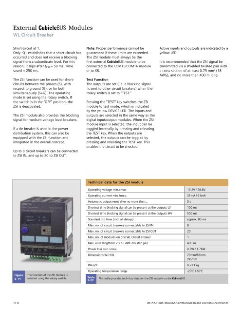
Figure<br />
2-14<br />
2/31<br />
The function of the ZSI module is<br />
selected using the rotary switch.<br />
Note: Proper performance cannot be<br />
guaranteed if these limits are exceeded.<br />
The ZSI module must always be the<br />
first external CubicleBUS module to be<br />
connected to the COM15/COM16 module<br />
or to X8.<br />
Test Function<br />
The outputs are set (i.e. a blocking signal<br />
is sent to other circuit breakers) when the<br />
rotary switch is set to “TEST.”<br />
Pressing the “TEST” key switches the ZSI<br />
module to test mode, which is indicated<br />
by the yellow DEVICE LED. The inputs and<br />
outputs are selected in the same way as the<br />
digital input/output modules. When the ZSI<br />
module input is selected, the input can be<br />
toggled internally by pressing and releasing<br />
the TEST key. When the outputs are<br />
selected, the outputs can be toggled by<br />
pressing and releasing the TEST key. This<br />
enables the circuit to be checked.<br />
Technical data for the ZSI module<br />
Operating voltage min./max. 19.2V / 28.8V<br />
Operating current min./max. 31mA / 61mA<br />
Automatic output reset after no more than... 3 s<br />
Shortest time blocking signal can be present at the outputs LV 100 ms<br />
Shortest time blocking signal can be present at the outputs MV 500 ms<br />
Standard trip time (incl. all delays) approx. 80 ms<br />
Max. no. of circuit breakers connectable to ZSI IN 8<br />
Max. no. of circuit breakers connectable to ZSI OUT 20<br />
Max. no. of modules on one <strong>WL</strong> <strong>Circuit</strong> Breaker 1<br />
Max. wire length for 2 x 18 AWG twisted pair 400 m<br />
Power loss min./max. 0.8W / 1.76W<br />
Dimensions W/H/D 70mm/86mm<br />
/95mm<br />
Weight 0.223 kg<br />
Operating temperature range -20°C / 60°C<br />
Table<br />
2-22<br />
This table provides technical data for the ZSI module on the CubicleBUS.<br />
Active inputs and outputs are indicated by a<br />
yellow LED.<br />
It is recommended that the ZSI signal be<br />
transmitted via a shielded twisted pair with<br />
a cross-section of at least 0.75 mm 2 (18<br />
AWG), and no more than 400 m long.<br />
<strong>WL</strong> PROFIBUS/MODBUS Communication and Electronic Accessories


