NanoLC 1D Plus and 2D System Operator's Manual - Eksigent
NanoLC 1D Plus and 2D System Operator's Manual - Eksigent
NanoLC 1D Plus and 2D System Operator's Manual - Eksigent
- No tags were found...

Create successful ePaper yourself
Turn your PDF publications into a flip-book with our unique Google optimized e-Paper software.
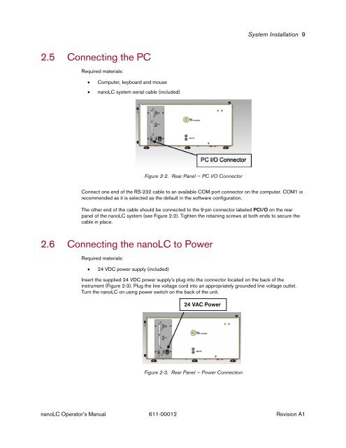
<strong>System</strong> Installation 92.5 Connecting the PCRequired materials:• Computer, keyboard <strong>and</strong> mouse• nanoLC system serial cable (included)Figure 2-2. Rear Panel — PC I/O ConnectorConnect one end of the RS-232 cable to an available COM port connector on the computer. COM1 isrecommended as it is selected as the default in the software configuration.The other end of the cable should be connected to the 9-pin connector labeled PCI/O on the rearpanel of the nanoLC system (see Figure 2-2). Tighten the retaining screws at both ends to secure thecable in place.2.6 Connecting the nanoLC to PowerRequired materials:• 24 VDC power supply (included)Insert the supplied 24 VDC power supply’s plug into the connector located on the back of theinstrument (Figure 2-3). Plug the line voltage cord into an appropriately grounded line voltage outlet.Turn the nanoLC on using power switch on the back of the unit.24 VAC PowerFigure 2-3. Rear Panel — Power ConnectionnanoLC Operator’s <strong>Manual</strong> 611-00012 Revision A1