NanoLC 1D Plus and 2D System Operator's Manual - Eksigent
NanoLC 1D Plus and 2D System Operator's Manual - Eksigent
NanoLC 1D Plus and 2D System Operator's Manual - Eksigent
- No tags were found...

You also want an ePaper? Increase the reach of your titles
YUMPU automatically turns print PDFs into web optimized ePapers that Google loves.
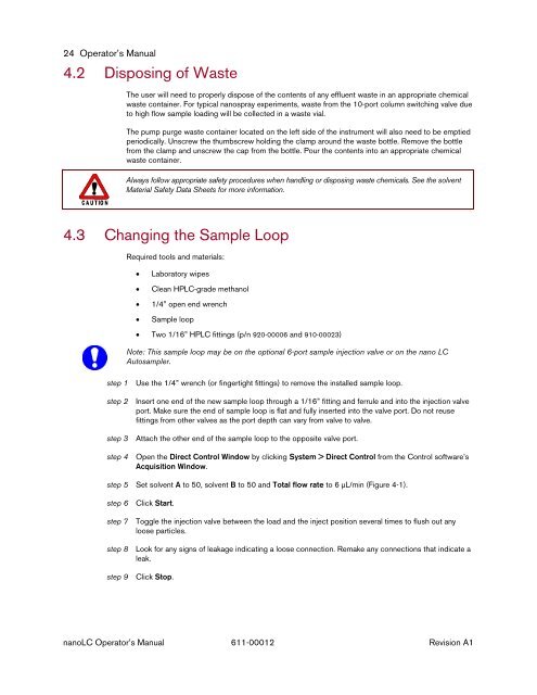
24 Operator’s <strong>Manual</strong>4.2 Disposing of WasteThe user will need to properly dispose of the contents of any effluent waste in an appropriate chemicalwaste container. For typical nanospray experiments, waste from the 10-port column switching valve dueto high flow sample loading will be collected in a waste vial.The pump purge waste container located on the left side of the instrument will also need to be emptiedperiodically. Unscrew the thumbscrew holding the clamp around the waste bottle. Remove the bottlefrom the clamp <strong>and</strong> unscrew the cap from the bottle. Pour the contents into an appropriate chemicalwaste container.Always follow appropriate safety procedures when h<strong>and</strong>ling or disposing waste chemicals. See the solventMaterial Safety Data Sheets for more information.4.3 Changing the Sample LoopRequired tools <strong>and</strong> materials:• Laboratory wipes• Clean HPLC-grade methanol• 1/4” open end wrench• Sample loop• Two 1/16” HPLC fittings (p/n 920-00006 <strong>and</strong> 910-00023)Note: This sample loop may be on the optional 6-port sample injection valve or on the nano LCAutosampler.step 1 Use the 1/4” wrench (or fingertight fittings) to remove the installed sample loop.step 2 Insert one end of the new sample loop through a 1/16” fitting <strong>and</strong> ferrule <strong>and</strong> into the injection valveport. Make sure the end of sample loop is flat <strong>and</strong> fully inserted into the valve port. Do not reusefittings from other valves as the port depth can vary from valve to valve.step 3 Attach the other end of the sample loop to the opposite valve port.step 4 Open the Direct Control Window by clicking <strong>System</strong> > Direct Control from the Control software’sAcquisition Window.step 5 Set solvent A to 50, solvent B to 50 <strong>and</strong> Total flow rate to 6 µL/min (Figure 4-1).step 6 Click Start.step 7 Toggle the injection valve between the load <strong>and</strong> the inject position several times to flush out anyloose particles.step 8 Look for any signs of leakage indicating a loose connection. Remake any connections that indicate aleak.step 9 Click Stop.nanoLC Operator’s <strong>Manual</strong> 611-00012 Revision A1