Novel Design of an Integrated Pulp Mill Biorefinery for the ...
Novel Design of an Integrated Pulp Mill Biorefinery for the ...
Novel Design of an Integrated Pulp Mill Biorefinery for the ...
Create successful ePaper yourself
Turn your PDF publications into a flip-book with our unique Google optimized e-Paper software.
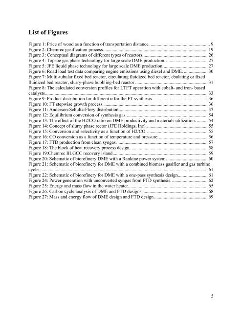
List <strong>of</strong> Figures<br />
Figure 1: Price <strong>of</strong> wood as a function <strong>of</strong> tr<strong>an</strong>sportation dist<strong>an</strong>ce. .................................................. 9<br />
Figure 2: Chemrec gasification process ........................................................................................ 19<br />
Figure 3: Conceptual diagrams <strong>of</strong> different types <strong>of</strong> reactors. ...................................................... 26<br />
Figure 4: Topsøe gas phase technology <strong>for</strong> large scale DME production. ................................... 27<br />
Figure 5: JFE liquid phase technology <strong>for</strong> large scale DME production. ..................................... 27<br />
Figure 6: Road load test data comparing engine emissions using diesel <strong>an</strong>d DME. .................... 30<br />
Figure 7: Multi-tubular fixed bed reactor, circulating fluidized bed reactor, ebulating or fixed<br />
fluidized bed reactor, slurry-phase bubbling-bed reactor ............................................................. 31<br />
Figure 8: The calculated conversion pr<strong>of</strong>iles <strong>for</strong> LTFT operation with cobalt- <strong>an</strong>d iron- based<br />
catalysts. ........................................................................................................................................ 33<br />
Figure 9: Product distribution <strong>for</strong> different α <strong>for</strong> <strong>the</strong> FT syn<strong>the</strong>sis ............................................... 36<br />
Figure 10: FT stepwise growth process. ....................................................................................... 36<br />
Figure 11: Anderson-Schultz-Flory distribution ........................................................................... 37<br />
Figure 12: Equilibrium conversion <strong>of</strong> syn<strong>the</strong>sis gas. .................................................................... 54<br />
Figure 13: The effect <strong>of</strong> <strong>the</strong> H2/CO ratio on DME productivity <strong>an</strong>d materials utilization. ......... 54<br />
Figure 14: Concept <strong>of</strong> slurry phase rector (JFE Holdings, Inc). ................................................... 55<br />
Figure 15: Conversion <strong>an</strong>d selectivity as a function <strong>of</strong> H2/CO. ................................................... 55<br />
Figure 16: CO conversion as a function <strong>of</strong> temperature <strong>an</strong>d pressure. ......................................... 56<br />
Figure 17: FTD production from cle<strong>an</strong> syngas. ............................................................................ 57<br />
Figure 18: The block <strong>of</strong> heat recovery process design. ................................................................ 58<br />
Figure 19:Chemrec BLGCC recovery isl<strong>an</strong>d ................................................................................ 59<br />
Figure 20: Schematic <strong>of</strong> biorefinery DME with a R<strong>an</strong>kine power system ................................... 60<br />
Figure 21: Schematic <strong>of</strong> biorefinery <strong>for</strong> DME with a combined biomass gasifier <strong>an</strong>d gas turbine<br />
cycle .............................................................................................................................................. 61<br />
Figure 22: Schematic <strong>of</strong> biorefinery <strong>for</strong> DME with a one-pass syn<strong>the</strong>sis design ......................... 61<br />
Figure 24: Power generation with unconverted syngas from FTD syn<strong>the</strong>sis. .............................. 62<br />
Figure 25: Energy <strong>an</strong>d mass flow in <strong>the</strong> water heater. .................................................................. 65<br />
Figure 26: Carbon cycle <strong>an</strong>alysis <strong>of</strong> DME <strong>an</strong>d FTD designs. ...................................................... 68<br />
Figure 27: Mass <strong>an</strong>d energy flow <strong>of</strong> DME design <strong>an</strong>d FTD design. ............................................ 69<br />
5


