36e Operator's Manual 2013.pdf - Marlow-Hunter, LLC
36e Operator's Manual 2013.pdf - Marlow-Hunter, LLC
36e Operator's Manual 2013.pdf - Marlow-Hunter, LLC
- No tags were found...

You also want an ePaper? Increase the reach of your titles
YUMPU automatically turns print PDFs into web optimized ePapers that Google loves.
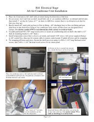
12V DCPORTDC AMPSSTBDSTART-STOP/PRIME24V DCSTATUS<strong>Hunter</strong> e36 • DC Electricstructions continuously within and at each end.7.3.3 LPG StoveThe breaker marked “LP Gas”, supplies power to theremote switch for your 2 burner gas stove. Refer to page5.14 for the arrangement layout of this system.7.3.3.1 Basic Stove Operation1. On standard battery charger model, turn on housebattery selector switch (under chart table).2. Turn on Main DC breaker at Battery Switch Panel.3. Turn on “LP Gas” breaker.4. Open valve to LPG bottle.5. Turn on LP gas solenoid, switch located on end ofNav Station.Note: Consult product manual for operating the stoveand other information on the unit.7.3.4 RefrigeratorsThe breaker marked “refrigerator”, on the 12 VoltDC Panel supplies power to the refrigerator aboardyour boat. Refer to Interior arrangement layouton page 4.16 for the location of the refrigerator.7.3.4.1 Basic Refrigerator Operation1. On standard battery charger model, turn on housebattery selector switch (under chart table).7.3.5 Bilge Pump SystemsYour boat is equipped with 1 main bilge pump and1 (Optional) emergency bilge pump. For locationsof the bilge pump systems, consult your MechanicalArrangement Drawing or the Sanitary Systems Drawing.The Bilge Pump System consists of a pump and a floatswitch. When the water level rises far enough to activatethe float switch, this activates the pump which lowers thewater level down to a point that the float switch stops thepower. Fig. 7.4 shows you the typical wiring.For more information about your bilge pump system, seeSanitary Systems.7.3.2 To manually operate your bilge pumps:Note: The power to the MDP does not need to be energized inorder to manually operate your bilge pumps.1. Locate the bilge pump switches at the Nav station andswitch them to the manual position.2. Another procedure to be used in extreme circumstancesinvolves locating the float switch and manually rotatingthe float handle on the side of the float switch to simulatethe float switch being underwater. This will energize thepump and the pump will operate.Battery Switch PanelMain Distribution Panel12 VOLT D.C.DC DISTRIBUTION PANELBATTERY TEST2. Turn on Main DC breaker at Main Breaker Panel.3. Turn on Refrigerator breaker.4. Set Thermostats to desired temperature.Note: If leaving unit on when away from boat be sureshore power cables are connected and battery chargeris on to prevent battery drain. (Optional inverterequipped models charge circuit is automatic if shorepower is connected and has power to Main DistributionPanel).Note: Consult product manual for operating the refrigeratorand other information on the unit.7.3.6 Shower SumpFigure 7.4The shower sump is part of the Sanitary System and7.6