

General Design Principles for DuPont Engineering Polymers - Module
General Design Principles for DuPont Engineering Polymers - Module
General Design Principles for DuPont Engineering Polymers - Module

You also want an ePaper? Increase the reach of your titles
YUMPU automatically turns print PDFs into web optimized ePapers that Google loves.
Part <strong>Design</strong> Considerations<br />
Part design is an important variable, frequently<br />
overlooked until tooling has been completed and<br />
attempts have been made to weld the first molded<br />
parts.<br />
a) Joint <strong>Design</strong><br />
Perhaps, the most critical facet of part design <strong>for</strong><br />
ultrasonic welding is joint design, particularly with<br />
materials which have a crystalline structure and a<br />
high melting point, such as <strong>DuPont</strong> engineering<br />
plastics. It is less critical when welding amorphous<br />
plastics. There are two basic types of joints, the<br />
shear joint and butt type joint.<br />
Shear Joint<br />
The shear joint is the preferred joint <strong>for</strong> ultrasonic<br />
welding. It was developed by engineers at <strong>DuPont</strong>’s<br />
Plastics Technical Center in Geneva in 1967, and has<br />
been used worldwide very successfully in many<br />
applications since that time. The basic shear joint with<br />
standard dimensions is shown in Figure 11.47 and<br />
11.48 be<strong>for</strong>e, during and after welding.<br />
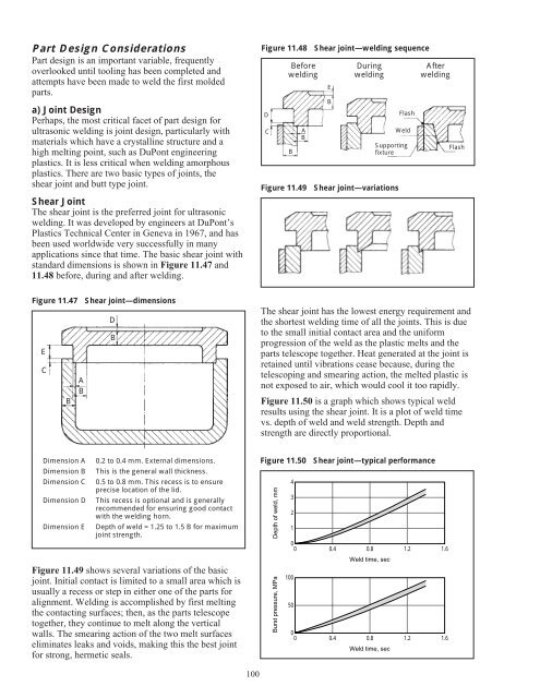
Figure 11.47 Shear joint—dimensions<br />
E<br />
C<br />
B<br />
A<br />
B<br />
D<br />
B<br />
Dimension A 0.2 to 0.4 mm. External dimensions.<br />
Dimension B This is the general wall thickness.<br />
Dimension C 0.5 to 0.8 mm. This recess is to ensure<br />
precise location of the lid.<br />
Dimension D This recess is optional and is generally<br />
recommended <strong>for</strong> ensuring good contact<br />
with the welding horn.<br />
Dimension E Depth of weld = 1.25 to 1.5 B <strong>for</strong> maximum<br />
joint strength.<br />
Figure 11.49 shows several variations of the basic<br />
joint. Initial contact is limited to a small area which is<br />
usually a recess or step in either one of the parts <strong>for</strong><br />
alignment. Welding is accomplished by first melting<br />
the contacting surfaces; then, as the parts telescope<br />
together, they continue to melt along the vertical<br />
walls. The smearing action of the two melt surfaces<br />
eliminates leaks and voids, making this the best joint<br />
<strong>for</strong> strong, hermetic seals.<br />
100<br />
Figure 11.48 Shear joint—welding sequence<br />
D<br />
C<br />
Be<strong>for</strong>e<br />
welding<br />
B<br />
A<br />
B<br />
E<br />
B<br />
During<br />
welding<br />
Flash<br />
Weld<br />
Supporting<br />
fixture<br />
Figure 11.49 Shear joint—variations<br />
After<br />
welding<br />
Flash<br />
The shear joint has the lowest energy requirement and<br />
the shortest welding time of all the joints. This is due<br />
to the small initial contact area and the uni<strong>for</strong>m<br />
progression of the weld as the plastic melts and the<br />
parts telescope together. Heat generated at the joint is<br />
retained until vibrations cease because, during the<br />
telescoping and smearing action, the melted plastic is<br />
not exposed to air, which would cool it too rapidly.<br />
Figure 11.50 is a graph which shows typical weld<br />
results using the shear joint. It is a plot of weld time<br />
vs. depth of weld and weld strength. Depth and<br />
strength are directly proportional.<br />
Figure 11.50 Shear joint—typical per<strong>for</strong>mance<br />
Depth of weld, mm<br />
Burst pressure, MPa<br />
4<br />
3<br />
2<br />
1<br />
0<br />
0 0.4 0.8<br />
1.2 1.6<br />
100<br />
50<br />
Weld time, sec<br />
0<br />
0 0.4 0.8<br />
1.2 1.6<br />
Weld time, sec


