

General Design Principles for DuPont Engineering Polymers - Module
General Design Principles for DuPont Engineering Polymers - Module
General Design Principles for DuPont Engineering Polymers - Module

Create successful ePaper yourself
Turn your PDF publications into a flip-book with our unique Google optimized e-Paper software.
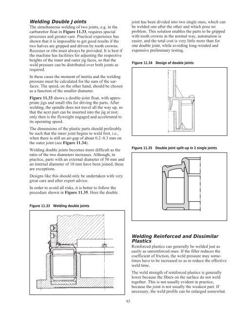
Welding Double Joints<br />
The simultaneous welding of two joints, e.g. in the<br />
carburettor float in Figure 11.33, requires special<br />
processes and greater care. Practical experience has<br />
shown that it is impossible to get good results if the<br />
two halves are gripped and driven by tooth crowns.<br />
Recesses or ribs must always be provided. It is best if<br />
the machine has facilities <strong>for</strong> adjusting the respective<br />
heights of the inner and outer jig faces, so that the<br />
weld pressure can be distributed over both joints as<br />
required.<br />
In these cases the moment of inertia and the welding<br />
pressure must be calculated <strong>for</strong> the sum of the surfaces.<br />
The speed, on the other hand, should be chosen<br />
as a function of the smaller diameter.<br />
Figure 11.33 shows a double-joint float, with appropriate<br />
jigs and small ribs <strong>for</strong> driving the parts. After<br />
welding, the spindle does not travel all the way up, so<br />
that the next part can be inserted into the jig at rest;<br />
only then is the flyweight engaged and accelerated to<br />
its operating speed.<br />
The dimensions of the plastic parts should preferably<br />
be such that the inner joint begins to weld first, i.e.,<br />
when there is still an air-gap of about 0.2–0.3 mm on<br />
the outer joint (see Figure 11.34).<br />
Welding double joints becomes more difficult as the<br />
ratio of the two diameters increases. Although, in<br />
practice, parts with an external diameter of 50 mm and<br />
an internal diameter of 10 mm have been joined, these<br />
are exceptions.<br />
<strong>Design</strong>s like this should only be undertaken with very<br />
great care and after expert advice.<br />
In order to avoid all risks, it is better to follow the<br />
procedure shown in Figure 11.35. Here the double<br />
Figure 11.33 Welding double joints<br />
93<br />
joint has been divided into two single ones, which can<br />
be welded one after the other and which pose no<br />
problem. This solution enables the parts to be gripped<br />
with tooth crowns in the normal way, automation is<br />
easier, and the total cost is very little more than <strong>for</strong><br />
one double joint, while avoiding long-winded and<br />
expensive preliminary testing.<br />
Figure 11.34 <strong>Design</strong> of double joints<br />
Figure 11.35 Double joint split-up in 2 single joints<br />
Welding Rein<strong>for</strong>ced and Dissimilar<br />
Plastics<br />
Rein<strong>for</strong>ced plastics can generally be welded just as<br />
easily as unrein<strong>for</strong>ced ones. If the filler reduces the<br />
coefficient of friction, the weld pressure may sometimes<br />
have to be increased so as to reduce the effective<br />
weld time.<br />
The weld strength of rein<strong>for</strong>ced plastics is generally<br />
lower because the fibers on the surface do not weld<br />
together. This is not usually evident in practice,<br />
because the joint is not usually the weakest part. If<br />
necessary, the weld profile can be enlarged somewhat.


