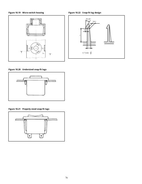
Figure 10.19 Micro-switch housing Figure 10.20 Undersized snap-fit lugs Figure 10.21 Properly sized snap-fit lugs 76 Figure 10.22 Snap-fit lug design l h 30–45° t h = 0.02 · t t2 ~ 3/4 t
11—Assembly Techniques, Category II Welding, Adhesive Bonding Spin Welding Introduction Rotation welding is the ideal method <strong>for</strong> making strong and tight joints between any thermoplastic parts which have symmetry of rotation. Engineers faced with the choice of either the ultrasonic or the spinwelding process will unhesitatingly prefer the latter, in view of the following advantages which it presents: • The investment required <strong>for</strong> identical production is lower with spinwelding than with ultrasonics. There are no special difficulties in construction the machinery from ordinary commercial machine parts, either wholly or partly in one’s own workshop. • The process is based on physical principles which can be universally understood and mastered. Once the tools and the welding conditions have been chosen correctly, results can be optimized merely by varying one single factor, namely the speed. • The cost of electrical control equipment is modest, even <strong>for</strong> fully automatic welding. • There is much greater freedom in the design of the parts, and no need to worry about projecting edges, studs or ribs breaking off. Molded in metal parts cannot work loose and damage any pre-assembled mechanical elements. Nor is it essential <strong>for</strong> the distribution of mass in the parts to be symmetrical or uni<strong>for</strong>m, as is the case with ultrasonic welding. If the relative position of the two components matters, then an ultrasonic or vibration welding process must be used. But, in practice, there are often cases in which this is essential only because the component has been badly designed. Parts should, as far as possible, be designed in such a way that positioning of the two components relative to each other is unnecessary. Basic <strong>Principles</strong> In spinwelding, as the name implies, the heat required <strong>for</strong> welding is produced by a rotating motion, simultaneously combined with pressure, and there<strong>for</strong>e the process is suitable only <strong>for</strong> circular parts. It is of course immaterial which of the two halves is held fixed and which is rotated. If the components are of different lengths, it is better to rotate the shorter one, to keep down the length of the moving masses. In making a selection from the methods and equipment described in detail below, the decisive factors 77 are the geometry of the components, the anticipated output, and the possible amount of capital investment. Because of the relatively small number of mechanical components needed, the equipment can sometimes be constructed by the user himself. In this way, serious defects in the welding process can often be pinpointed, some examples of which will be described later. Practical Methods The most commonly used methods can be divided roughly into two groups as follows: Pivot Welding During welding the device holding the rotating part is engaged with the driving shaft, the two parts being at the same time pressed together. After completion of the welding cycle, the rotating jig is disengaged from the shaft, but the pressure is kept up <strong>for</strong> a short time, depending on the type of plastic. Inertia Welding The energy required <strong>for</strong> welding is first stored up in a flywheel, which is accelerated up to the required speed; this flywheel also carries the jig and one of the plastic parts. Then the parts are <strong>for</strong>ced together under high pressure, at which point the kinetic energy of the flywheel is converted into heat by friction, and it comes to a stop. In practice this method has proved the more suitable one, and will there<strong>for</strong>e be described in more detail. Pivot Welding Pivot Welding on a Lathe Easily the simplest, but also the most cumbersome welding method in this group, pivot welding can be carried out on any suitable sized lathe. Figure 11.01 illustrates the setup. One of the parts to be welded, a, is clamped by b, which may be an ordinary chuck, a self-locking chuck, a compressed air device, or any other suitable device, so long as it grips the part firmly, centers and drives it. The spring-loaded counterpoint c in the tailstock must be capable of applying the required pressure, and should be able to recoil 5–10 mm. The cross-slide d should also, if possible, be equipped with a lever. The plastic part a1 should have some sort of projecting rib, edge, etc., so that the stop e can prevent it from rotating. The actual welding will then proceed as follows: a) The part a is fixed into the clamp, and then its companion piece a1 is placed in position, where it is kept under pressure by the spring-loaded point. b) The cross-slide d travels <strong>for</strong>ward, so that the stop e is brought below one of the projections on a1. c) The spindle is engaged or the motor switched on.
- Page 1 and 2:
dDuPont Engineering Polymers Genera
- Page 3 and 4:
8—Gears . . . . . . . . . . . . .
- Page 5 and 6:
1—General Introduction This secti
- Page 7 and 8:
Prototyping the Design In order to
- Page 9 and 10:
2—Injection Molding The Process a
- Page 11 and 12:
As a general rule, use the minimum
- Page 13 and 14:
Figure 3.11 Cored holes Figure 3.12
- Page 15 and 16:
Figure 3.19 Mold-ejection of rounde
- Page 17 and 18:
• Zytel ® nylon resin—Parts of
- Page 19 and 20:
4—Structural Design Short Term Lo
- Page 21 and 22:
Form of section Area A d d R R 1 1
- Page 23 and 24:
Table 4.03. Formulas for Stresses a
- Page 25 and 26:
Form of bar; manner of loading and
- Page 27 and 28:
Figure 4.01 Creep Stress (S), MPa (
- Page 29 and 30: Figure 4.05 Creep in flexure of Zyt
- Page 31 and 32: Example 1 It there are no restricti
- Page 33 and 34: Determine the moment of inertia and
- Page 35 and 36: Figure 4.11 Stress curves The compu
- Page 37 and 38: Rim Design Rim design requirements
- Page 39 and 40: Figure 5.08 Chair Seat Zytel ® 71
- Page 41 and 42: Cantilever Springs Tests were condu
- Page 43 and 44: 7—Bearings Bearings and bushings
- Page 45 and 46: debris is moved around continuously
- Page 47 and 48: Table 7.01 Coefficient of Friction*
- Page 49 and 50: Figure 7.15: Connecting rod spheric
- Page 51 and 52: 8—Gears Introduction Delrin ® ac
- Page 53 and 54: 9—Gear Design Allowable Tooth Ben
- Page 55 and 56: Delrin ® 500. See the section on D
- Page 57 and 58: Figure 9.06 Sizes of gear teeth of
- Page 59 and 60: The following additional examples i
- Page 61 and 62: In practice, the most commonly used
- Page 63 and 64: Driving Gear Meshing Gear Table 9.0
- Page 65 and 66: A full-throated worm gear is shown
- Page 67 and 68: Worm Material Gear Material Possibl
- Page 69 and 70: 10—Assembly Techniques Introducti
- Page 71 and 72: For these materials, the finer thre
- Page 73 and 74: Table 10.01 Self-Threading Screw Pe
- Page 75 and 76: Figures 10.07 and 10.08 show calcul
- Page 77 and 78: Undercut Snap-Fits In order to obta
- Page 79: Cantilever Lug Snap-Fits The second
- Page 83 and 84: Figure 11.03 Drill spindle position
- Page 85 and 86: Inertia Welding By far the simplest
- Page 87 and 88: Machines for Inertia Welding The pr
- Page 89 and 90: This is not always easy, because ap
- Page 91 and 92: The holder a, will have equal and o
- Page 93 and 94: Calculations for Inertia Welding To
- Page 95 and 96: If, for example, the angles of the
- Page 97 and 98: Welding Double Joints The simultane
- Page 99 and 100: Figure 11.37 Commercial bench-type
- Page 101 and 102: Heat is generated throughout the pa
- Page 103 and 104: Figure 11.45 Tapered or stepped hor
- Page 105 and 106: Weld strength is therefore determin
- Page 107 and 108: ) General Part Design The influence
- Page 109 and 110: eticule in the eye piece is suitabl
- Page 111 and 112: For this reason, if the strength of
- Page 113 and 114: Figure 11.64A shows a variation whi
- Page 115 and 116: 3. Vibrations, generated either by
- Page 117 and 118: If one part is only vibrated at twi
- Page 119 and 120: Another joint design, with flash tr
- Page 121 and 122: Figure 11.82. A linear welded motor
- Page 123 and 124: B) Commercial linear and angular we
- Page 125 and 126: Hot Plate Welding of Zytel ® One o
- Page 127 and 128: Figure 11.94 Applications of riveti
- Page 129 and 130: Tolerances may be difficult to hold
- Page 131 and 132:
are used in either hand- or power-o
- Page 133 and 134:
ather than scrape, these drills wil
- Page 135 and 136:
The polishing operation is performe