

General Design Principles for DuPont Engineering Polymers - Module
General Design Principles for DuPont Engineering Polymers - Module
General Design Principles for DuPont Engineering Polymers - Module

You also want an ePaper? Increase the reach of your titles
YUMPU automatically turns print PDFs into web optimized ePapers that Google loves.
Figure 3.22 Correct termination of threads<br />
Figure 3.23 Suggested end clearance on threads<br />
Threads—Effect of Creep<br />
When designing threaded assemblies of metal to<br />
plastic, it is preferable to have the metal part external<br />
to the plastic. In other words, the male thread should<br />
be on the plastic part. However, in a metal/plastic<br />
assembly, the large difference in the coefficient of<br />
linear thermal expansion between the metal and<br />
plastic must be carefully considered. Thermal stresses<br />
created because of this difference will result in creep<br />
or stress relaxation of the plastic part after an extended<br />
period of time if the assembly is subject to temperature<br />
fluctuations or if the end use temperature is<br />
elevated. If the plastic part must be external to the<br />
metal, a metal backup sleeve may be needed as shown<br />
in Figure 3.24.<br />
Figure 3.24<br />
0.8 mm (1/32″)<br />
GOOD POOR<br />
0.8 mm (1/32″)<br />
0.8 mm (1/32″)<br />
0.8 mm (1/32″)<br />
0.8 mm<br />
(1/32″)<br />
12<br />
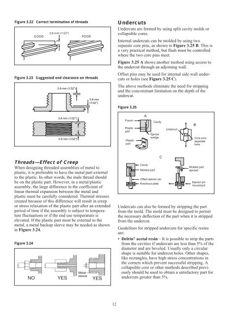
Undercuts<br />
Undercuts are <strong>for</strong>med by using split cavity molds or<br />
collapsible cores.<br />
Internal undercuts can be molded by using two<br />
separate core pins, as shown in Figure 3.25 B. This is<br />
a very practical method, but flash must be controlled<br />
where the two core pins meet.<br />
Figure 3.25 A shows another method using access to<br />
the undercut through an adjoining wall.<br />
Offset pins may be used <strong>for</strong> internal side wall undercuts<br />
or holes (see Figure 3.25 C).<br />
The above methods eliminate the need <strong>for</strong> stripping<br />
and the concomitant limitation on the depth of the<br />
undercut.<br />
Figure 3.25<br />
Punch<br />
Plastic<br />
part<br />
Plastic<br />
part<br />
A<br />
Cavity<br />
Molded part<br />
Cavity<br />
Ejector<br />
wedge<br />
C<br />
Offset ejector pin<br />
Knockout plate<br />
Undercut<br />
B<br />
Core pins<br />
separate<br />
here<br />
Molded part<br />
ejected<br />
Ejector pin<br />
movement<br />
Undercuts can also be <strong>for</strong>med by stripping the part<br />
from the mold. The mold must be designed to permit<br />
the necessary deflection of the part when it is stripped<br />
from the undercut.<br />
Guidelines <strong>for</strong> stripped undercuts <strong>for</strong> specific resins<br />
are:<br />
• Delrin ® acetal resin—It is possible to strip the parts<br />
from the cavities if undercuts are less than 5% of the<br />
diameter and are beveled. Usually only a circular<br />
shape is suitable <strong>for</strong> undercut holes. Other shapes,<br />
like rectangles, have high stress concentrations in<br />
the corners which prevent successful stripping. A<br />
collapsible core or other methods described previously<br />
should be used to obtain a satisfactory part <strong>for</strong><br />
undercuts greater than 5%.


