

General Design Principles for DuPont Engineering Polymers - Module
General Design Principles for DuPont Engineering Polymers - Module
General Design Principles for DuPont Engineering Polymers - Module

Create successful ePaper yourself
Turn your PDF publications into a flip-book with our unique Google optimized e-Paper software.
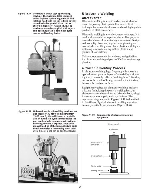
Figure 11.37 Commercial bench-type spinwelding<br />
machine. The basic model is equipped<br />
with a 3-phase squirrel cage motor. The<br />
rotating head with the jigs is fixed directly<br />
onto the double guided piston rod as<br />
shown in Figures 11.12 and 11.13. The<br />
machine an also be supplied with adjustable<br />
speed, turntable, automatic cycle<br />
control and feeding device.<br />
Figure 11.38 Universal inertia spinwelding machine, see<br />
also Figure 11.13 <strong>for</strong> welding parts from<br />
15–80 mm. By the addition of a turntable<br />
and an automatic cycle control device the<br />
unit can be made semi-automatic without<br />
involving too much expense. Even with<br />
manual feeding of the turntable (two parts<br />
simultaneously), a remarkably short total<br />
cycle time of 2 sec can be easily acheived.<br />
95<br />
Ultrasonic Welding<br />
Introduction<br />
Ultrasonic welding is a rapid and economical technique<br />
<strong>for</strong> joining plastic parts. It is an excellent<br />
technique <strong>for</strong> assembly of mass produced, high quality<br />
products in plastic materials.<br />
Ultrasonic welding is a relatively new technique. It is<br />
used with ease with amorphous plastics like polystyrene<br />
which have a low softening temperature. <strong>Design</strong><br />
and assembly, however, require more planning and<br />
control when welding amorphous plastics with higher<br />
softening temperatures, crystalline plastics and<br />
plastics of low stiffness.<br />
This report presents the basic theory and guidelines<br />
<strong>for</strong> ultrasonic welding of parts of <strong>DuPont</strong> engineering<br />
plastics.<br />
Ultrasonic Welding Process<br />
In ultrasonic welding, high frequency vibrations are<br />
applied to two parts or layers of material by a vibrating<br />
tool, commonly called a “welding horn.” Welding<br />
occurs as the result of heat generated at the interface<br />
between the parts or surfaces.<br />
Equipment required <strong>for</strong> ultrasonic welding includes<br />
a fixture <strong>for</strong> holding the parts, a welding horn, an<br />
electromechanical transducer to drive the horn, a high<br />
frequency power supply and a cycle timer. The<br />
equipment diagrammed in Figure 11.39 is described<br />
in detail later. Typical ultrasonic welding machines<br />
currently available are shown in Figure 11.40.<br />
Figure 11.39 Components of ultrasonic welding<br />
equipment<br />
Transducer or<br />
converter<br />
Welding horn<br />
Plastic parts<br />
Holding fixture<br />
Power supply<br />
Cycle timer


