

General Design Principles for DuPont Engineering Polymers - Module
General Design Principles for DuPont Engineering Polymers - Module
General Design Principles for DuPont Engineering Polymers - Module

You also want an ePaper? Increase the reach of your titles
YUMPU automatically turns print PDFs into web optimized ePapers that Google loves.
Table 7.03<br />
Max. PV Values Without Lubrication<br />
Material MPa · m/min<br />
Zytel ® 101 6<br />
Delrin ® 100/500 10<br />
Delrin ® 500 CL 15<br />
Delrin ® 500 AF 25<br />
Hytrel ® 5556/5526 2<br />
Figure 7.08 Definitions of bearing dimensions<br />
d = Shaft diameter, mm<br />
l = length of bearing, mm<br />
v = Peripheral speed, m/min<br />
P = Overall load, N<br />
V<br />
d<br />
<strong>Design</strong> Examples<br />
Gear Bearings<br />
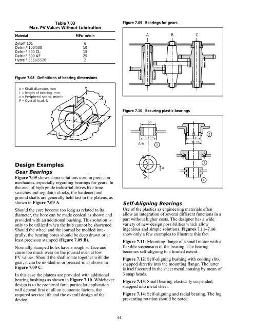
Figure 7.09 shows some solutions used in precision<br />
mechanics, especially regarding bearings <strong>for</strong> gears. In<br />
the case of high grade industrial drives like time<br />
switches and regulator clocks, the hardened and<br />
ground shafts are generally held fast in the platens, as<br />
shown in Figure 7.09 A.<br />
Should the core become too long as related to its<br />
diameter, the bore can be made conical as shown and<br />
provided with an additional bushing. This solution is<br />
only to be utilized when the hub cannot be shortened.<br />
Should the wheel and the journal be molded integrally,<br />
the bearing bores should be deep drawn or at<br />
least precision stamped (Figure 7.09 B).<br />
Normally stamped holes have a rough surface and<br />
cause too much wear on the journal even at low<br />
PV values. Should the shaft rotate together with the<br />
gear, it can be molded-in or pressed-in as shown in<br />
Figure 7.09 C.<br />
In this case the platens are provided with additional<br />
bearing bushings as shown in Figure 7.10. Whichever<br />
design is to be preferred <strong>for</strong> a particular application<br />
will depend first of all on economic factors, the<br />
required service life and the overall design of the<br />
device.<br />
s<br />
P<br />
l<br />
44<br />
Figure 7.09 Bearings <strong>for</strong> gears<br />
A B C<br />
Figure 7.10 Securing plastic bearings<br />
A-A<br />
A<br />
d<br />
d + 3%<br />
1<br />
A<br />
d<br />
d + 3%<br />
Self-Aligning Bearings<br />
Use of the plastics as engineering materials often<br />
allow an integration of several different functions in a<br />
part without higher costs. The designer has a wide<br />
variety of new design possibilities which allow<br />
ingenious and simple solutions. Figures 7.11–7.16<br />
show only a few examples to illustrate this fact.<br />
Figure 7.11: Mounting flange of a small motor with a<br />
flexible suspension of the bearing. The bearing<br />
becomes self-aligning to a limited extent.<br />
Figure 7.12: Self-aligning bushing with cooling slits,<br />
snapped directly into the mounting flange. The latter<br />
is itself secured in the sheet metal housing by mean of<br />
3 snap heads.<br />
Figure 7.13: Small bearing elastically suspended,<br />
snapped into metal sheet.<br />
Figure 7.14: Self-aligning and radial bearing. The lug<br />
preventing rotation should be noted.<br />
3<br />
4<br />
2


