

General Design Principles for DuPont Engineering Polymers - Module
General Design Principles for DuPont Engineering Polymers - Module
General Design Principles for DuPont Engineering Polymers - Module

Create successful ePaper yourself
Turn your PDF publications into a flip-book with our unique Google optimized e-Paper software.
The guide below, referring to Figure 3.15, will aid in<br />
eliminating part cracking or tear out of the plastic parts.<br />
d = diameter<br />
b = d<br />
c = d<br />
D = d<br />
t = thickness<br />
For a blind hold, thickness of the bottom should be no<br />
less than 1 ⁄ 6 the hole diameter in order to eliminate<br />
bulging (see Figure 3.16 A). Figure 3.16 B shows a<br />
better design in which the wall thickness is uni<strong>for</strong>m<br />
throughout and there are no sharp corners where stress<br />
concentrations could develop.<br />
Figure 3.15 Hole design<br />
Figure 3.16 Blind holes<br />
Threads<br />
When required, external and internal threads can be<br />
automatically molded into the part, eliminating the<br />
need <strong>for</strong> mechanical thread-<strong>for</strong>ming operations.<br />
External Threads<br />
Parts with external threads can be molded in two<br />
ways. The least expensive way is to locate the parting<br />
line on the centerline of the thread, Figure 3.17. If this<br />
is not acceptable, or the axis of the thread is in the<br />
direction of mold-opening, the alternative is to equip<br />
the mold with an external, thread-unscrewing device.<br />
10<br />
Figure 3.17 Molding external threads without side core<br />
Internal Threads<br />
Internal threads are molded in parts by using automatic<br />
unscrewing devices or collapsible cores to<br />
produce partial threads. A third method is to use handloaded<br />
threaded inserts that are removed from the<br />
mold with the part.<br />
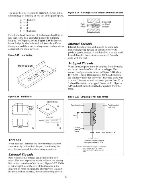
Stripped Threads<br />
When threaded parts are to be stripped from the mold,<br />
the thread must be of the roll or round type. The<br />
normal configuration is shown in Figure 3.18 where<br />
R = 0.288 × pitch. Requirements <strong>for</strong> thread stripping<br />
are similar to those <strong>for</strong> undercuts. Threaded parts with<br />
a ratio of diameter to wall thickness greater than 20 to<br />
1 should be able to be stripped from a mold. Figures<br />
3.19 and 3.20 show the method of ejection from the<br />
mold.<br />
Figure 3.18 Stripping of roll-type thread<br />
Female tool<br />
Pitch<br />
Stripper<br />
plate or<br />
sleeve<br />
R<br />
Clearance between stripper<br />
and apex of thread = 1/2 R<br />
Source: Injection-Mould <strong>Design</strong> Fundamentals<br />
A. B. Glanville and E. N. Denton<br />
Machinery Publishing Co., London<br />
1965<br />
Fixed threaded<br />
male core<br />
Depth of thread = R


