

General Design Principles for DuPont Engineering Polymers - Module
General Design Principles for DuPont Engineering Polymers - Module
General Design Principles for DuPont Engineering Polymers - Module

Create successful ePaper yourself
Turn your PDF publications into a flip-book with our unique Google optimized e-Paper software.
Rib <strong>Design</strong><br />
As discussed earlier, the use of ribs to improve rigidity<br />
and reduce weight is acceptable only when such<br />
product improvement is essential. This restriction of<br />
course is due to the possible surface and warpage<br />
problems that can be caused by ribbing. Once the need<br />
<strong>for</strong> ribs has been established, they should not be used<br />
arbitrarily, but rather to provide a specified improvement<br />
in rigidity, weight reduction or both. Two types<br />
of ribbing are considered here: cross-ribbing and<br />
unidirectional. In both cases, graphical plots are<br />
presented to simplify problem solution.<br />
Guidelines <strong>for</strong> selecting rib proportions are shown in<br />
Figure 4.07. Height of the rib should be determined<br />
by structural design, and in some cases could be<br />
limited by molding conditions. Fillet radius at base of<br />
rib should be 1 ⁄ 2 the rib thickness.<br />
Figure 4.07<br />
Cross-Ribbing<br />
Most housings—tape cassettes, pressure containers,<br />
meter shrouds, and just plain boxes—have one<br />
functional requirement in common: the need <strong>for</strong><br />
rigidity when a load is applied. Since rigidity is<br />
directly proportional to the moment of inertia of the<br />
housing cross section, it is physically simple (though<br />
sometimes mathematically complex) to replace a<br />
constant wall section part with a ribbed structure with<br />
the same rigidity but less weight. To simplify such<br />
analysis, the curve in Figure 4.08 has been developed<br />
to help determine the feasibility of using a ribbed<br />
structure in a product. The curve describes the dimensional<br />
relationship between simple flat plates and<br />
cross-ribbed plates (Figure 4.09) having identical<br />
values of moment of inertia. The base of the graph<br />
shows values from 0 to 0.2 <strong>for</strong> the product of the<br />
non-ribbed wall thickness (t A) and the number of ribs<br />
per inch (N) divided by the width of the plate (W).<br />
The W value was taken as unity in the development of<br />
the curve; thus it is always one (1).<br />
26<br />
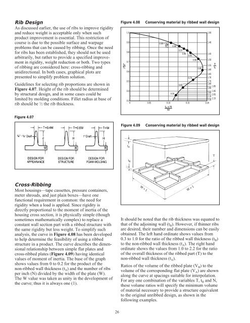
Figure 4.08 Conserving material by ribbed wall design<br />
1.0<br />
0.9<br />
0.8<br />
0.7<br />
tB<br />
tA<br />
0.6<br />
T<br />
tA<br />
0.5<br />
0.4<br />
0.3<br />
0 0.05<br />
0.10<br />
0.15<br />
2.20<br />
0.20<br />
2.15<br />
2.10 2.05<br />
2.00 1.95<br />
0.99 = VB<br />
VA 0.98<br />
1.40<br />
0.97<br />
0.96<br />
0.95<br />
1.45<br />
0.90<br />
0.80<br />
1.50<br />
1.55<br />
1.60<br />
1.65<br />
0.70<br />
1.70<br />
1.75<br />
0.60<br />
1.80<br />
1.85<br />
1.90<br />
0.50<br />
tA x N<br />
W<br />
Figure 4.09 Conserving material by ribbed wall design<br />
tA<br />
t B<br />
W = 1<br />
W = 1<br />
It should be noted that the rib thickness was equated to<br />
that of the adjoining wall (tB). However, if thinner ribs<br />
are desired, their number and dimensions can be easily<br />
obtained. The left hand ordinate shows values from<br />
0.3 to 1.0 <strong>for</strong> the ratio of the ribbed wall thickness (tB) to the non-ribbed wall thickness (tA). The right hand<br />
ordinate shows the values from 1.0 to 2.2 <strong>for</strong> the ratio<br />
of the overall thickness of the ribbed part (T) to the<br />
non-ribbed wall thickness (tA). Ratios of the volume of the ribbed plate (VB) to the<br />
volume of the corresponding flat plate (VA) are shown<br />
along the curve at spacings suitable <strong>for</strong> interpolation.<br />
For any one combination of the variables T, tB and N,<br />
these volume ratios will specify the minimum volume<br />
of material necessary to provide a structure equivalent<br />
to the original unribbed design, as shown in the<br />
following examples.<br />
1.00<br />
T


